Detecting and measuring interference contained within a digital carrier

a digital carrier and interference detection technology, applied in the field of detection of interference and noise in transmitted signals, can solve the problems of interference (including noise) showing up in-band to a transmitted carrier, can be very difficult to detect, and affect the receive quality of the transmitted digital carrier. significant, and the effect of interferen

Active Publication Date: 2009-12-29
GLOWLINK COMMUNICATIONS TECHNOLOGY INC
View PDF42 Cites 28 Cited by
  • Summary
  • Abstract
  • Description
  • Claims
  • Application Information

AI Technical Summary

Problems solved by technology

Interference (including noise) showing up in-band to a transmitted carrier is a common problem in wireless communication systems.
For example, in satellite communication systems, interference can be caused by, but is not limited to, isolation degradation of cross-polarized signals, adjacent satellite traffic, locally received terrestrial signals, or an unauthorized transmission.
In many cases, interference can be very difficult to detect, however, its impact on the receive quality of the transmitted digital carrier can be significant.
Although this approach can be effective, it causes a service interruption that can last for many hours.
In some cases, interference is not the problem, and the service was interrupted unnecessarily.

Method used


Image

  • Detecting and measuring interference contained within a digital carrier
  • Detecting and measuring interference contained within a digital carrier
  • Detecting and measuring interference contained within a digital carrier

Examples


Embodiment Construction

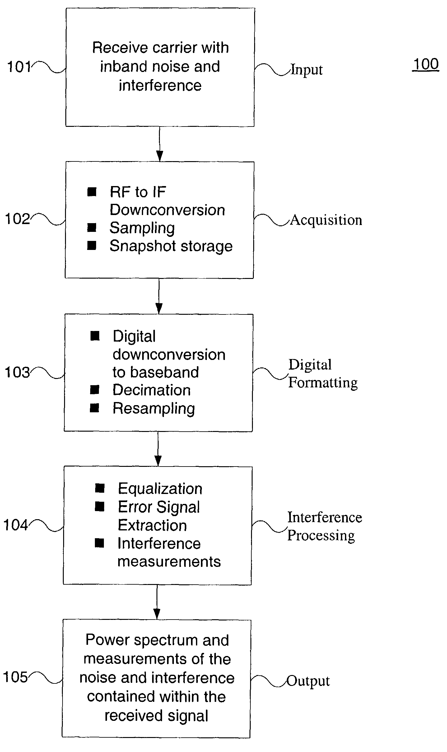
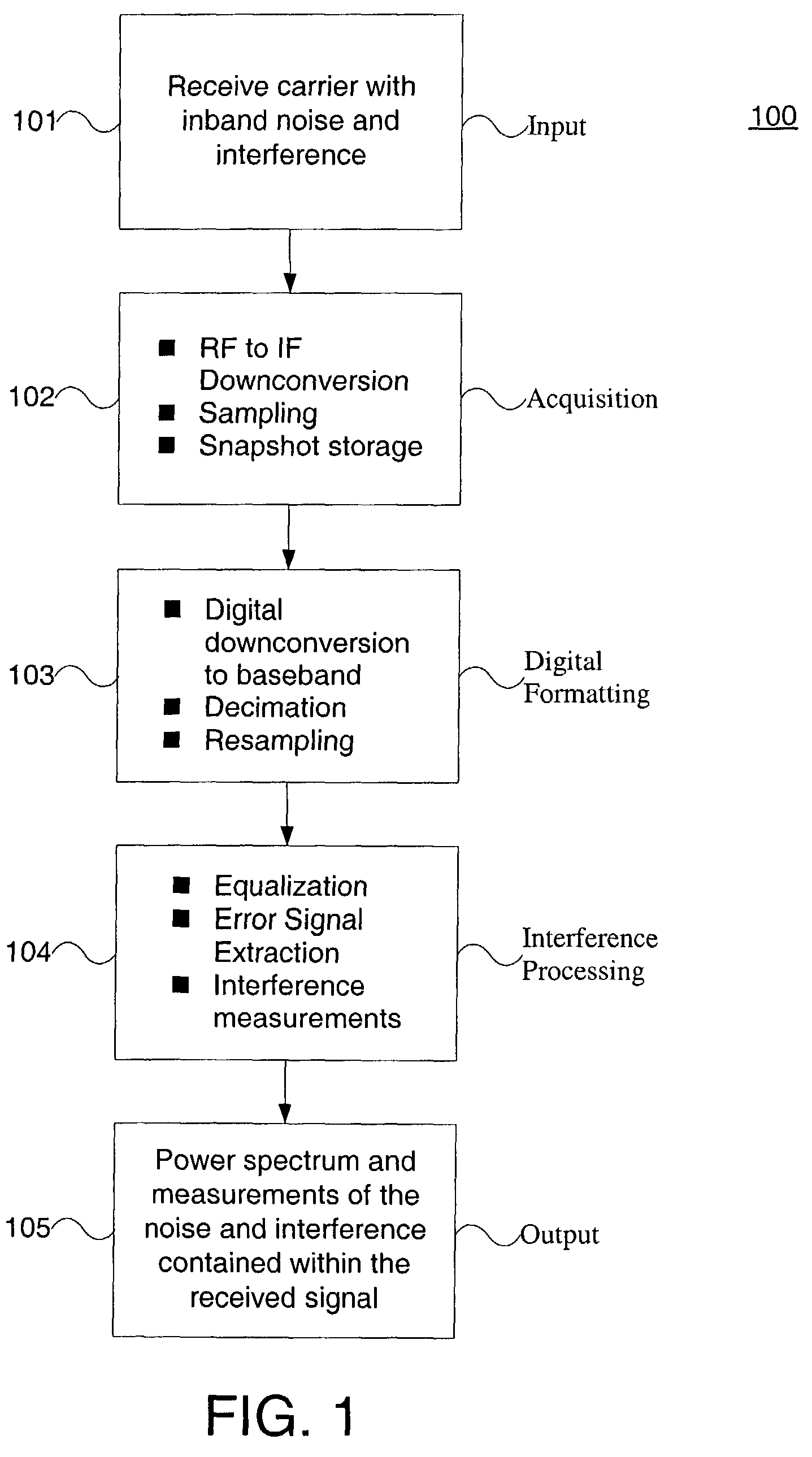
[0014]FIG. 1 shows a flow diagram of a process 100 in accordance with an aspect of the present invention. A signal, which contains noise and interference, is received in a step 101. The signal is down-converted to an intermediate frequency (IF) and then digitized by a sampling device, in an acquisition step 102. The digital samples are stored in memory for further processing, also in the acquisition step 102. Using the stored samples, the signal is processed to create a re-sampled baseband version of the received signal, in a digital formatting step 103. Using this re-sampled baseband signal, an equalized error signal is created, in an interference processing step 104. This error signal is further processed to create a power spectrum of the underlying noise and interference contained in the received carrier, also in the interference processing step 104. This power spectrum of the noise and interference can be measured for interfering signals as well as displayed to the user, in an o...


PUM


Abstract

A method and system for measuring noise and or interference in a communications signal without taking the signal out of service. In the present invention the communications signal is converted from an RF signal into an IF signal. The IF signal is then digitized and stored. The stored signal is processed to determine the interference signal. The interference signal is calculated from an error vector produced by a blind equalizer demodulator. The interference signal is extracted and presented to a user.

Description

[0001]This application claims the benefit of U.S. Provisional Application Ser. No. 60 / 361,493, filed Mar. 4, 2002, the contents of which are hereby incorporated by reference.FIELD OF THE INVENTION[0002]The invention relates to detection of interference and noise in a transmitted signal.DESCRIPTION OF THE RELATED ART[0003]Interference (including noise) showing up in-band to a transmitted carrier is a common problem in wireless communication systems. For example, in satellite communication systems, interference can be caused by, but is not limited to, isolation degradation of cross-polarized signals, adjacent satellite traffic, locally received terrestrial signals, or an unauthorized transmission. In many cases, interference can be very difficult to detect, however, its impact on the receive quality of the transmitted digital carrier can be significant.[0004]The most common approach to determining the presence of interference is to temporarily remove the service (the transmitted carri...

Claims


Application Information

Patent Timeline
Patent Type & Authority Patents(United States)
IPC IPC(8): H03D1/04H03H7/30H04B1/10H04L1/00H04L1/20H04L17/00H04L25/03
CPCH04B1/1027H04B17/345H04L1/20
Inventor CHU, JEFFREY C.DOWNEY, MICHAEL L.
Owner GLOWLINK COMMUNICATIONS TECHNOLOGY INC
Why Eureka
Try Eureka