Ultrasonic motor and electronic device using the same

a technology of ultrasonic motor and electronic device, applied in piezoelectric/electrostrictive/magnetostrictive devices, piezoelectric/electrostriction/magnetostriction machines, electrical apparatus, etc., can solve the problems of reducing the efficiency and achieve the effect of improving the output of ultrasonic motor, enhancing vibration caused by the vibrating body, and increasing the drive force of the moving body

Inactive Publication Date: 2010-01-05
FUKOKU CO LTD
View PDF7 Cites 6 Cited by
  • Summary
  • Abstract
  • Description
  • Claims
  • Application Information

AI Technical Summary

Benefits of technology

[0006]Accordingly, it is an object of the present invention to provide an ultrasonic motor whose output is improved by enhancing the exciting force of a vibration caused on a vibrating body having a rectangular portion.
[0008]With the configuration, the vibration caused on the vibrating body can be enhanced to increase the drive force of the moving body, thereby improving the output of the ultrasonic motor.
[0009]Because the exciting force of the vibration (particularly, bending vibration) caused on the vibrating body can be increased according to the present invention, the acquired output of the moving body becomes greater, thus making the efficiency of the ultrasonic motor higher. This makes it possible to achieve size reduction and reduction in consumed power of an electronic device having the ultrasonic motor of the present invention mounted therein.

Problems solved by technology

However, the ultrasonic motor using the vibration of a rectangular plate is disadvantageous in that the exciting force of the vibration (particularly, bending vibration) caused on the rectangular plate to be the vibrating body is weak, so that the ultrasonic motor has a smaller output and lower efficiency.

Method used


Image

  • Ultrasonic motor and electronic device using the same
  • Ultrasonic motor and electronic device using the same
  • Ultrasonic motor and electronic device using the same

Examples


first embodiment

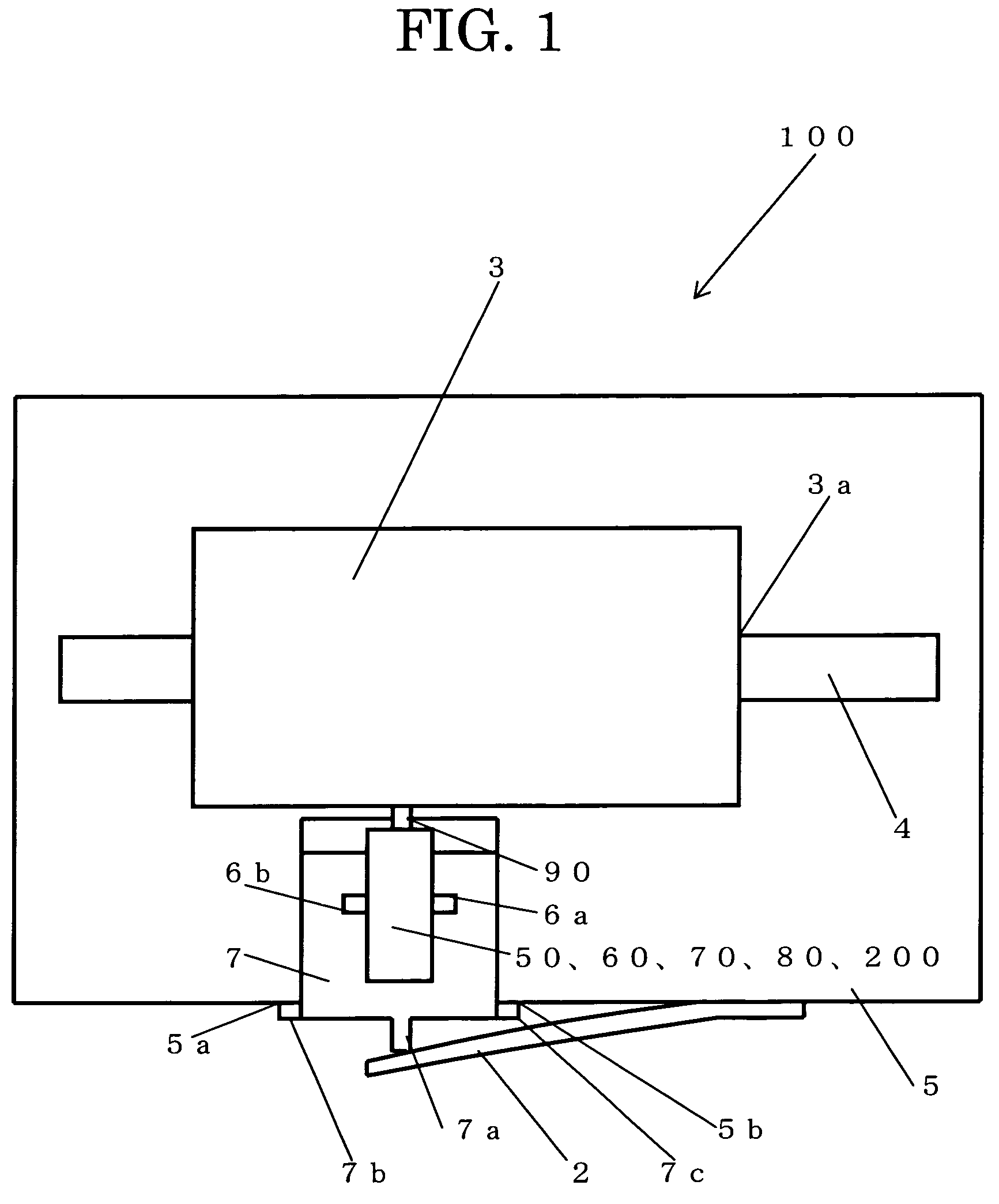
[0028]An ultrasonic motor according to a first embodiment of the present invention and an electronic device using the same will be described referring to the diagrams. To begin with, the configuration of an ultrasonic motor 100 of the invention using the ultrasonic motor 100 as a stage (electronic device) 100 will be described by way of example referring to FIG. 1.

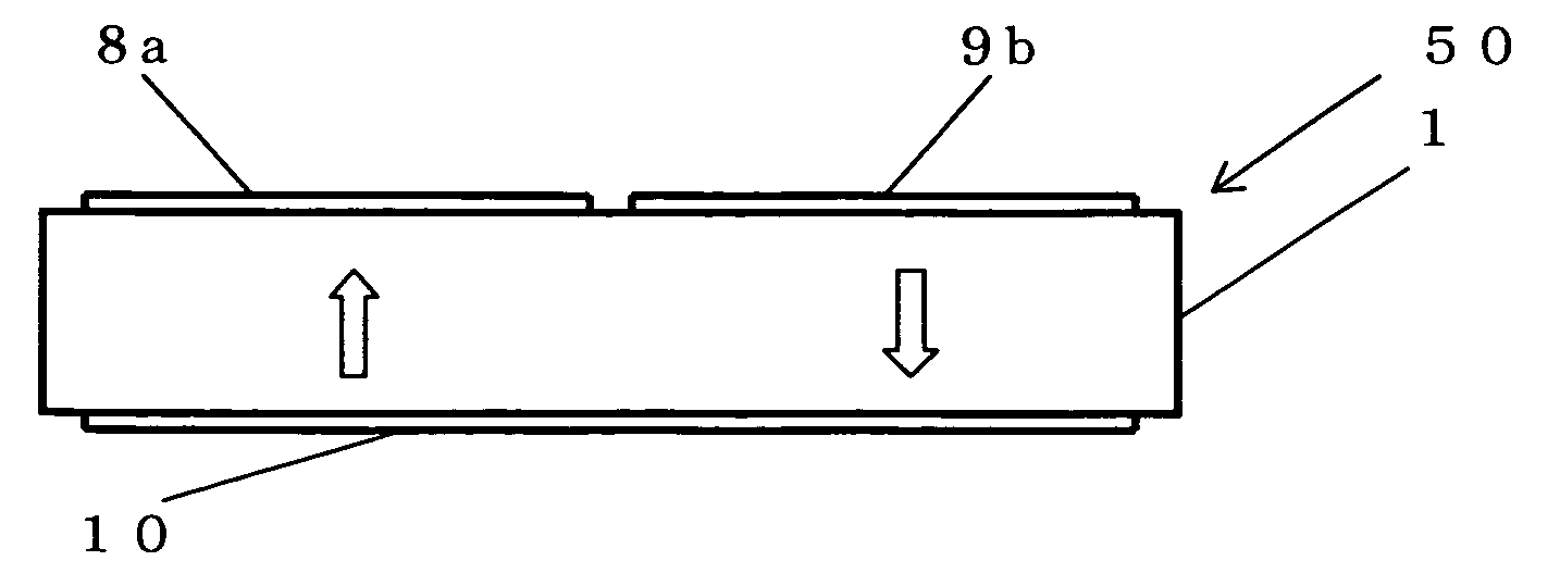
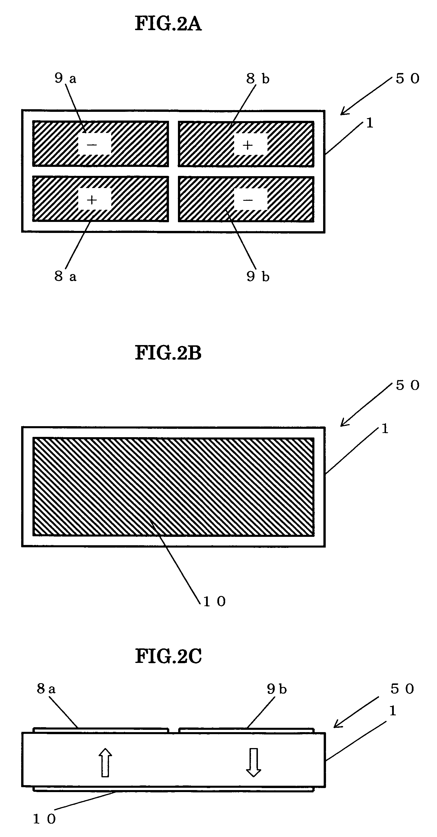
[0029]The ultrasonic motor 100 of the invention generally includes a vibrating body 50 comprised of a rectangular piezoelectric element 1, a moving body 3 which is in contact with and is frictionally driven by the vibrating body 50, and a pressurizing member 2 which generates a contact pressure between the vibrating body 50 and the moving body 3.

[0030]A rail 4 provided on a plate-like fixed member 5 is engaged with a guide groove 3a provided along the moving direction of the moving body 3, so that the moving body 3 is guided so as to be movable in the lengthwise direction of the rail 4. Although the guide structure provide...

second embodiment

[0040]A second embodiment of an ultrasonic motor of the present invention will be described below referring to FIGS. 6A and 6B. The following description is centered on differences from the illustrated vibrating body 50 of the first embodiment or the electrode structure of the vibrating body 60. An electrode (third electrode) 14 is provided at the top surface (one side) of a piezoelectric element 11 at a portion located at the center portion of three areas separated by lines connecting points which separates two short sides of the rectangular portion into three portions, electrodes 12a, 12b, 13a, 13b are provided at four areas obtained by further separating two end portions of the three areas by a line connecting center points of two long sides of the piezoelectric element 11, two electrodes 12a, 12b provided at two orthogonal portions of the four areas constitute first electrodes 12, and two electrodes 13a, 13b provided at other two orthogonal portions of the four areas constitute ...

third embodiment

[0046]A third embodiment of an ultrasonic motor of the present invention will be described below referring to FIGS. 9A and 9B. The following description is centered on differences from the illustrated vibrating bodies 50 and 60 of the first embodiment and the second embodiment, or the electrode structure of a vibrating body 70.

[0047]An electrode 18 is provided at the top surface (one side) of a piezoelectric element 20 at one of two areas separated by a line connecting points which separates two short sides of the piezoelectric element 20 into two portions, and an electrode 16 and an electrode 17 are provided at two areas obtained by further separating the other area by a line connecting center points of two long sides of the piezoelectric element 20. An electrode 19 is provided substantially over the entire bottom side (the other side) of the piezoelectric element 20. With the electrode 19 serving as the GND, a high voltage is applied to the electrodes 16, 17, 18, so that the piezo...


PUM


Abstract

Disclosed is an ultrasonic motor whose output is improved by enhancing the exciting force of a vibration caused on a vibrating body having a rectangular portion. The ultrasonic motor includes the vibrating body having a piezoelectric element, and a moving body which contacts the vibrating body. The phases of two difference vibrations caused on the vibrating body are changed to make the moving direction of the moving body or the vibrating body itself variable by selecting whether to apply a drive signal to first electrodes provided at one side of the piezoelectric element or to apply a drive signal to second electrodes provided at a portion whose polarization direction differs from that of the first electrodes.

Description

BACKGROUND OF THE INVENTION[0001]1. Field of the Invention[0002]The present invention relates to an ultrasonic motor which frictionally drives a moving body with the vibration of a vibrating body, and an electronic device using the same, and, particularly, to an ultrasonic motor which drives a moving body with a vibration obtained by combining a longitudinal vibration and a bending vibration caused on a rectangular vibrating body.[0003]2. Description of the Related Art[0004]Recently, with size reduction, functional enhancement and reduction in consumed power of electronic devices, attention has been paid to ultrasonic motors as an actuator to move operational parts, and achievement of the adoption thereof is increasing. Particularly, many linear type ultrasonic motors which can be driven directly are used in electronic devices, such as a precision stage, which need high-accuracy positioning. There is known a typical linear type ultrasonic motor which utilizes a combined vibration of...

Claims


Application Information

Patent Timeline
Patent Type & Authority Patents(United States)
IPC IPC(8): H01L41/08
CPCH01L41/0913H02N2/026H10N30/2023
Inventor IINO, AKIHIROWATANABE, SATOSHI
Owner FUKOKU CO LTD
Why Eureka
Try Eureka