Information processing apparatus with a cache memory and information processing method

a technology of information processing apparatus and cache memory, applied in the field of reading data, to achieve the effect of reducing cache misses and faster data read

Active Publication Date: 2010-01-05
SONY COMPUTER ENTERTAINMENT INC
View PDF20 Cites 4 Cited by
  • Summary
  • Abstract
  • Description
  • Claims
  • Application Information

AI Technical Summary

Benefits of technology

[0006]The present invention has been achieved in view of the foregoing problem. It is thus an object of the present invention to provide an information processing apparatus and an information processing method for reducing cache misses for the sake of faster data read.
[0009]The control unit may suppress occurrence of the refill operation when the plurality of operating units access an identical memory address with a predetermined time difference. When the control unit receives a plurality of refill requests to an identical memory address, it may suspend the refill operation corresponding to the refill request of the second henceforth. When the control unit receives a plurality of refill requests to an identical memory address, it may also suspend entry lock corresponding to the refill request of the second henceforth. Moreover, the control unit may accumulate a predetermined number of refill requests occurring from cache misses before performing the refill operation.
[0014]Still another aspect of the present invention is an information processing method. This method comprises: arbitrating between a plurality of refill requests occurring from cache misses from a plurality of operating units accessing a cache memory, so as to suppress occurrence of thrashing in the cache memory; and performing a refill from a main memory to the cache memory in accordance with an arbitrated refill request. The aforementioned arbitration may suppress occurrence of the refill when the plurality of operating units access an identical memory address with a predetermined time difference. The occurrence of the refill may be suppressed until a predetermined number of refill requests are accumulated.

Problems solved by technology

Moreover, the control unit may accumulate a predetermined number of refill requests occurring from cache misses before performing the refill operation.

Method used


Image

  • Information processing apparatus with a cache memory and information processing method
  • Information processing apparatus with a cache memory and information processing method
  • Information processing apparatus with a cache memory and information processing method

Examples


first embodiment

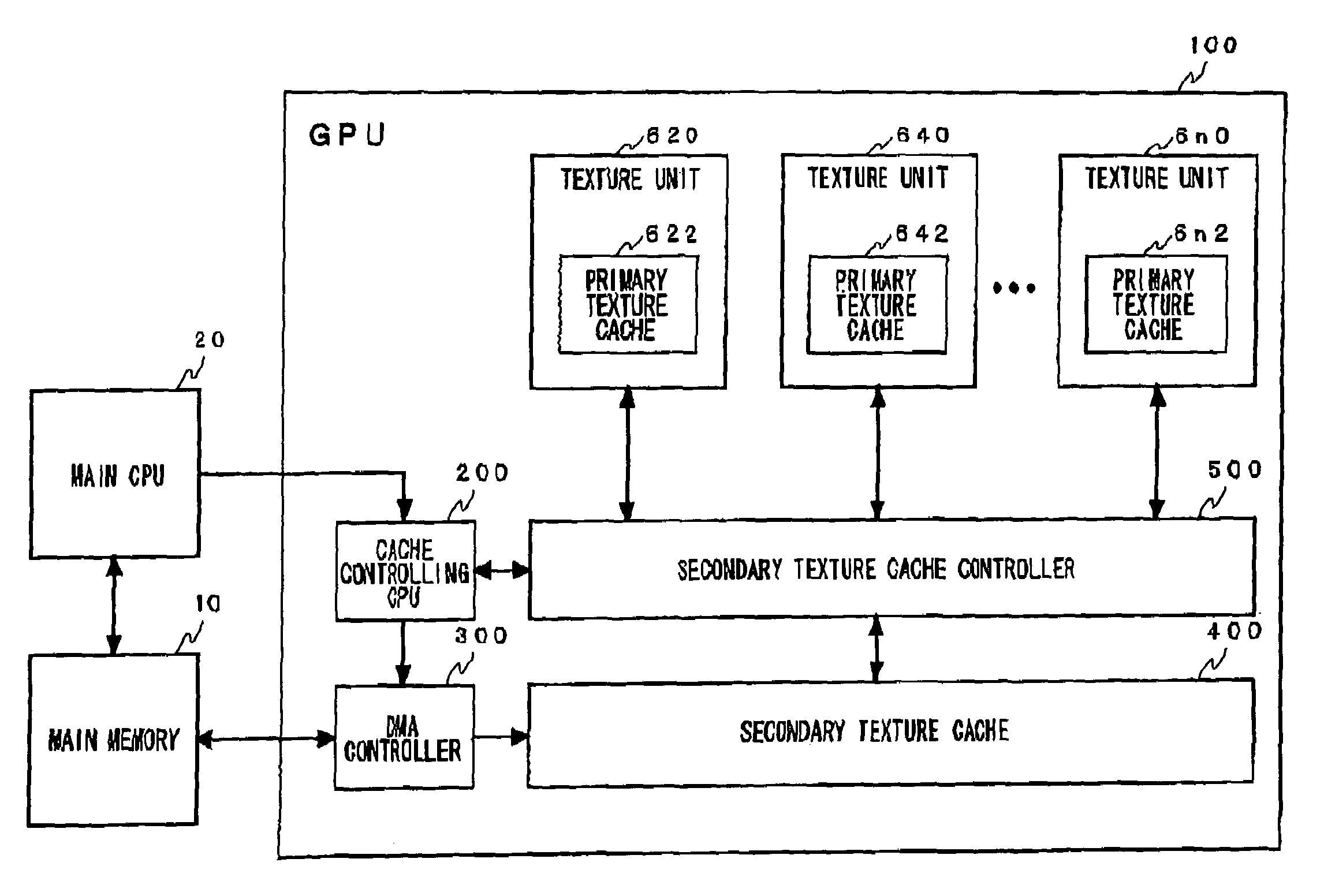
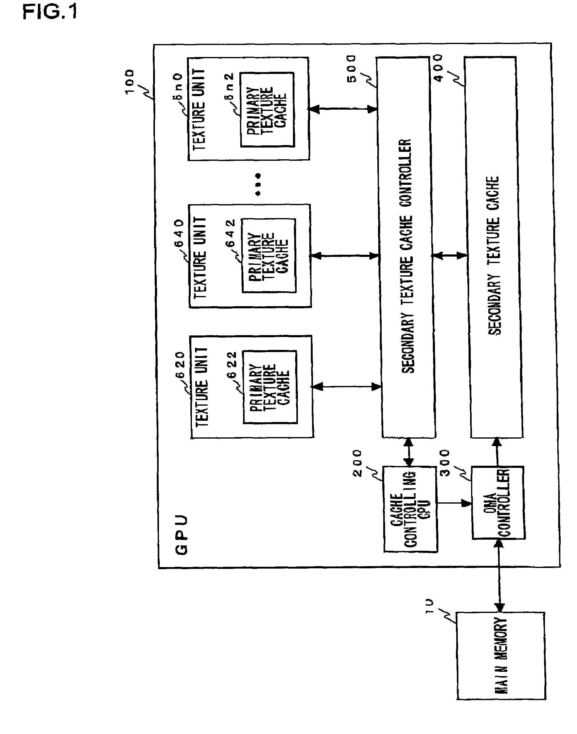
[0034]FIG. 1 is a block diagram showing the configuration of a main memory 10 and a graphics processing unit (GPU) 100 according to a The main memory 10 is the main memory of the system, and is composed of a DRAM or the like. In the present embodiment, the main memory 10 chiefly contains texture data. The GPU 100 is a semiconductor chip for carrying out calculations and rendering necessary for three-dimensional graphic display. The GPU 100 incorporates a plurality of texture units 620 to 6n0 which correspond to a plurality of not-shown shader units. The incorporation of the plurality of units improves the rendering speed for the sake of smoother scene transition and the like.

[0035]The texture units 620 to 6n0 have primary texture caches 622 to 6n2, respectively. The texture unit 620 receives parameter inputs for specifying texture data from the not-shown shader unit, and designates an address in the main memory space to request texture-constituting texel data from the primary textu...

second embodiment

[0065]FIG. 6 is a block diagram showing the configuration of a main memory 10 and a GPU 100 according to a FIG. 6 shows a configuration in which an intermediate buffer 350 is added to between the DMA controller 300 and the secondary texture cache 400 of the configuration of FIG. 1. Since the components other than the intermediate buffer 350 are the same as in FIG. 1, description thereof will be omitted here. The intermediate buffer 350 is a memory area which temporality stores texture data to be refilled from the main memory 10 to the secondary texture cache 400 by the DMA controller 300. When the texture data is stored, the intermediate buffer 350 issues a control signal for informing the cache controlling CPU 200 of it. Then, at the same time with or after a predetermined delay since the issuance of the control signal, the intermediate buffer 350 outputs the stored texture data to the secondary texture cache 400.

[0066]FIG. 7 is a flowchart showing an operation example of the syst...

third embodiment

[0069]FIG. 8 is a block diagram showing the configuration of a main memory 10, a main CPU 20, and a GPU 100 according to a FIG. 8 shows a configuration in which a main CPU 20 is added to the configuration of FIG. 1. Since the components other than the main CPU 20 are the same as in FIG. 1, description thereof will be omitted here. The main CPU 20 executes a program such as a game program, and predicts next texture data necessary for the texture units 620 to 6n0 in performing the texture mapping of the program. The main CPU 20 generates a DMA transfer instruction for prefetching this texture data from the main memory 10 to the secondary texture cache 400, and outputs it to the cache controlling CPU 200. The cache controlling CPU 200 issues this DMA transfer instruction to the DMA controller 300.

[0070]FIG. 9 is a flowchart showing a first operation example of the system according to the third embodiment. Initially, the cache controlling CPU 200 divides a plurality of ways of the seco...


PUM


Abstract

A secondary texture cache is used commonly by a plurality of texture units, and stores part of texture data in a main memory. A cache controlling CPU controls a refill operation from the main memory to the secondary texture cache in accordance with cache misses of the plurality of texture units, so as to suppress occurrence of thrashing in the secondary texture cache. The cache controlling CPU suppresses occurrence of the refill operation when the plurality of operating units access an identical memory address with a predetermined time difference.

Description

BACKGROUND OF THE INVENTION[0001]1. Field of the Invention[0002]The present invention relates to a technology for reading data from a main memory at higher speed, and more particularly to a technology for using a cache memory for acceleration.[0003]2. Description of the Related Art[0004]In recent years, processors have been improved dramatically in the operating frequency. In contrast, dynamic random access memories (DRAMS) typically used as main memories have not been so much improved in the operating frequency as the processors. Taking advantage of the processor performances thus requires some contrivance. The access times of the main memories have been reduced by using the technique of interposing a cache memory between a main memory and a processor.[0005]Nevertheless, even if the processor accesses the cache for a designated address, the cache does not always contain the desired data. In such cases, a cache miss occurs to require a refill from the main memory. When cache misses ...

Claims


Application Information

Patent Timeline
Patent Type & Authority Patents(United States)
IPC IPC(8): G06F12/08G06F13/00
CPCG06F12/0844G06F12/0864G06F12/0862G06F2212/6024
Inventor SASAKI, NOBUOYAMAZAKI, TAKESHIKUNIMATSU, ATSUSHIYASUKAWA, HIDEKI
Owner SONY COMPUTER ENTERTAINMENT INC
Why Eureka
Try Eureka