
Unit for conveying packs of tobacco products

a technology for conveying units and tobacco products, which is applied in the direction of transportation and packaging, shock-sensitive articles, packaging goods types, etc., can solve the problems of generating wear, unable to apply additional items to the packet, and damage to the packet propelled forward at the high operating speed of modern cigarette packers

Inactive Publication Date: 2010-01-12
GD SPA
View PDF11 Cites 2 Cited by
  • Summary
  • Abstract
  • Description
  • Claims
  • Application Information

AI Technical Summary

Benefits of technology

The present invention is a device for conveying products that has two conveyors with pockets that feed products to a user machine. The device also has sensors to detect the presence of products in the pockets of the second conveyor. The device has placement means that direct products into the pockets of the first conveyor, creating an unbroken chain of products that flow downstream of the transfer point. The technical effect of this invention is to create a seamless connection between two conveyor systems, ensuring a smooth transfer of products without any interruptions.

Problems solved by technology

These non-rectilinear stretches of the conveying path can cause damage to packets propelled forward at the high operating speeds of modern cigarette packers.
In particular, it will often happen that the corner of one packet rubs against the flank face of the packet in front, generating wear.
A further problem connected with random spacing of the packets is that the dynamic by which they are carried along the path cannot be controlled, so that it is not possible to apply additional items to the packets, such as coupons and / or leaflets, before their entry into the cellophaner.
More particularly, given that the packets do not advance in a regularly spaced succession, it is not possible with this type of feed system to predict when there are going to be gaps on the conveyor, and the recycle hopper comes into operation only when the cigarette packer is at standstill.
Even with the recycle hopper installed and in operation, consequently, there will always be unpredictable gaps in the flow of packets directed along the main conveyor toward the cellophaner, and the resulting empty spaces reduce the efficiency of the machine considerably.

Method used


Image

  • Unit for conveying packs of tobacco products
  • Unit for conveying packs of tobacco products
  • Unit for conveying packs of tobacco products

Examples


Embodiment Construction

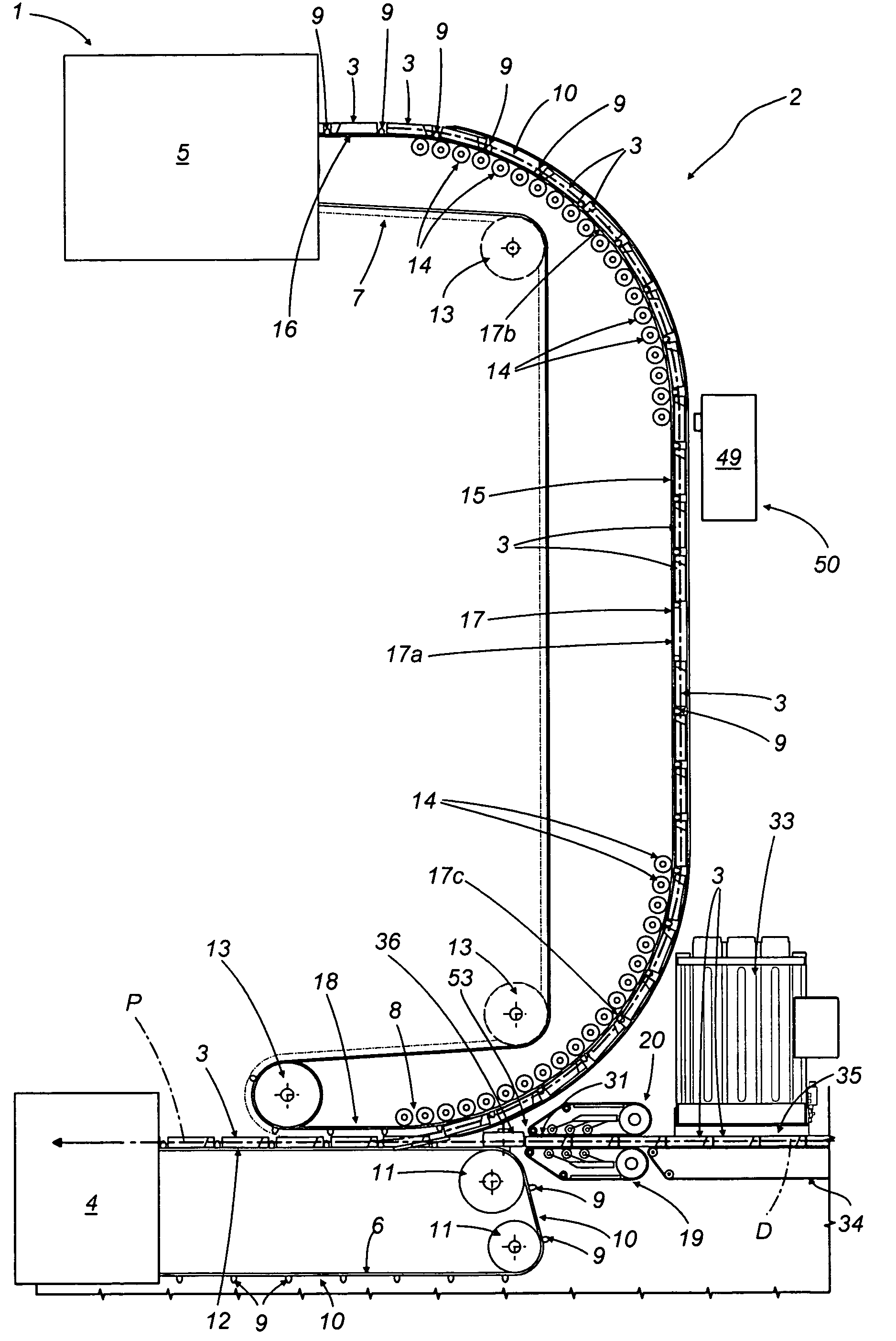
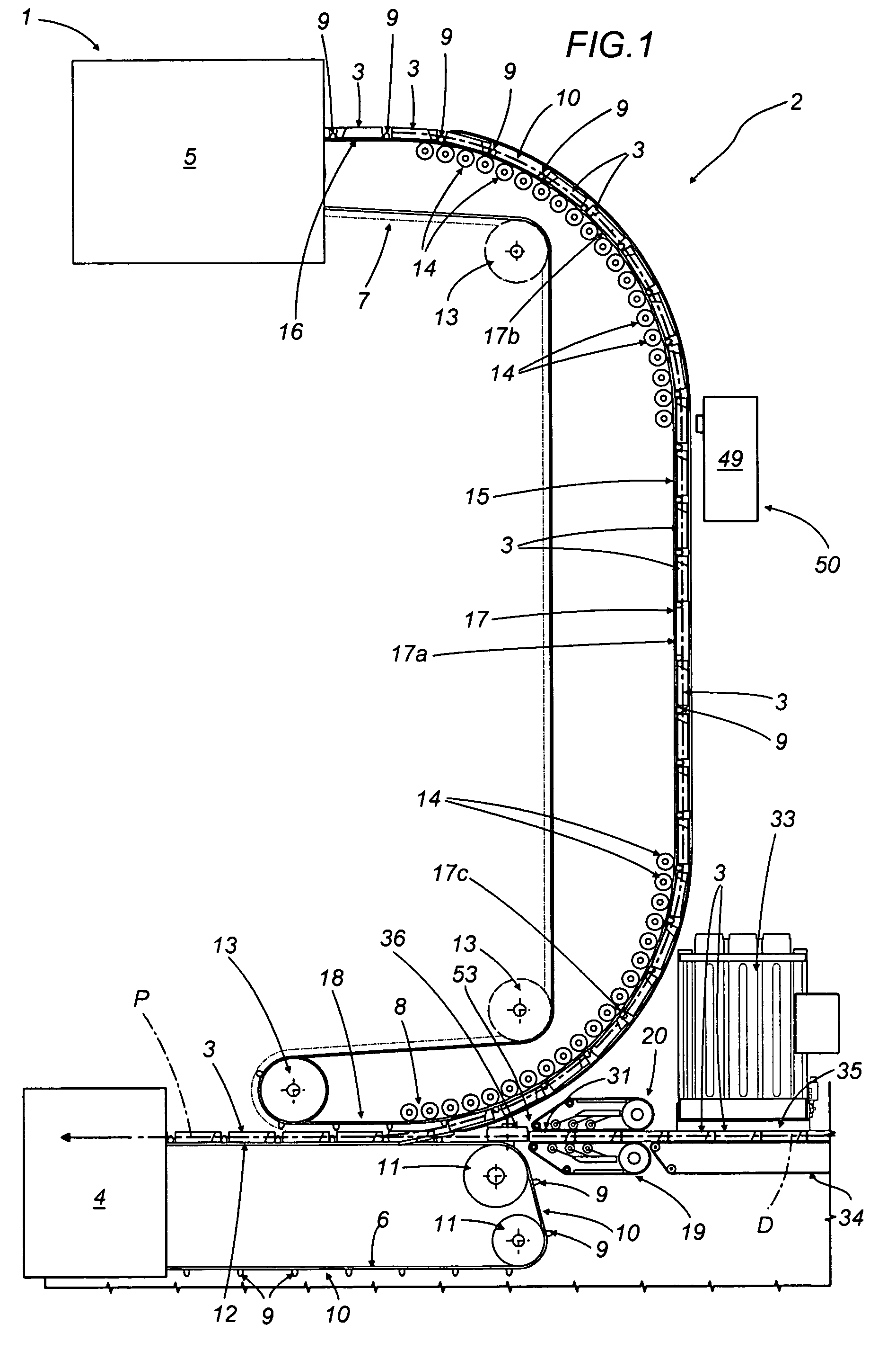
[0023]Referring to FIG. 1, numeral 1 shows a portion of a cigarette packing line, in its entirety.

[0024]The line 1 in question comprises a unit 2 by which packets 3 of cigarettes are conveyed to a user machine such as a cellophaner, represented schematically in FIG. 1 by a block denoted 4.

[0025]The packets 3 are turned out by an upstream unit consisting for example in a cigarette packer, shown schematically in FIG. 1 as a block denoted 5, and directed along the conveying unit 2 following a feed path denoted P.

[0026]The conveying unit 2 includes a first conveyor 6, set in continuous motion, from which packets 3 are directed into the aforementioned user machine 4, and a second conveyor 7, likewise set in continuous motion, from which packets 3 are directed onto the first conveyor 6. In an alternative embodiment of the unit 2, the conveyors 6 and 7 might be driven intermittently.

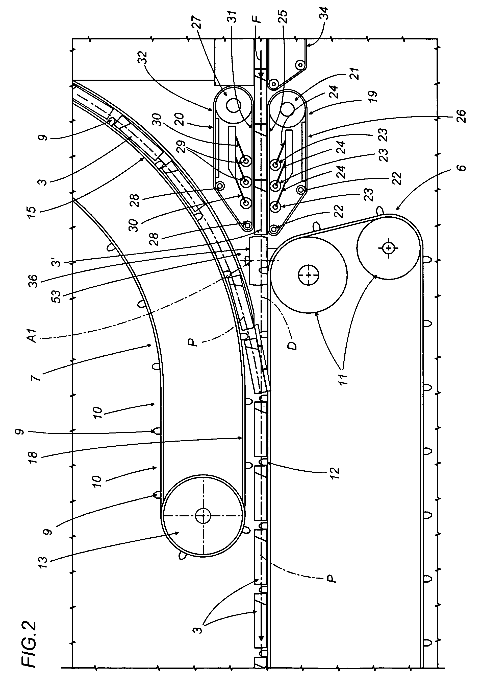
[0027]The advancing packets 3 pass from the second conveyor 7 onto the first conveyor 6 at a transfer point ...


PUM

PropertyMeasurementUnit
lengthaaaaaaaaaa
operating speedsaaaaaaaaaa
areaaaaaaaaaaa

Abstract

Packets of cigarettes are conveyed from a packer to a cellophaner by a unit utilizing a first pocket conveyor connected to the infeed of the cellophaner, and a second pocket conveyor by which packets are directed onto the first conveyor at a transfer point; the unit is also equipped with a sensor that will check whether or not each pocket of the second conveyor is occupied by a packet, and a placement mechanism, interlocked to the sensor, of which the function is to fill any empty pockets of the first conveyor with packets recycled from the cellophaner.

Description

[0001]This application claims priority to Italian Patent Application No. BO2004A000494, filed Aug. 3, 2004, which is incorporated by reference herein.BACKGROUND OF THE INVENTION[0002]The present invention relates to a unit for conveying products.[0003]In particular, the present invention relates to a unit for conveying products to a user machine, and more exactly a unit comprising a first and a second conveyor set in continuous motion.[0004]The invention finds application, to advantage, in the art field of conveying systems for packets of cigarettes, to which reference is made explicitly in the specification albeit implying no limitation in scope.[0005]In a typical cigarette packaging line, packets turned out by a cigarette packer are directed into a cellophaner, which proceeds to envelop each one in an overwrapping of polypropylene; the packets are supplied to the cellophaner by a first conveyor carrying the main flow from the packer, randomly spaced, and by a second recycle convey...

Claims


Application Information

Patent Timeline
Patent Type & Authority Patents(United States)
IPC IPC(8): B65B35/26B65B23/00
CPCB65G47/082
Inventor FEDERICI, LUCAMILANDRI, FRANCESCONEGRINI, STEFANO
Owner GD SPA
Learn More