Exhaust gas purification system

An exhaust gas purification system and exhaust gas technology, applied in the field of purification systems, can solve problems such as poor exhaust gas purification effect

Inactive Publication Date: 2020-12-08
魏荣宗
View PDF0 Cites 0 Cited by
  • Summary
  • Abstract
  • Description
  • Claims
  • Application Information

AI Technical Summary

Problems solved by technology

However, the purification effect of the current exhaust gas purification equipment

Method used


Image

  • Exhaust gas purification system
  • Exhaust gas purification system
  • Exhaust gas purification system

Examples


Embodiment Construction

[0024] Before the present invention is described in detail, it should be noted that in the following description, similar components are denoted by the same numerals.

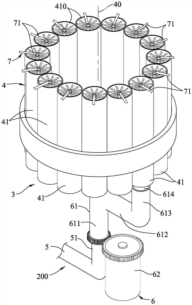
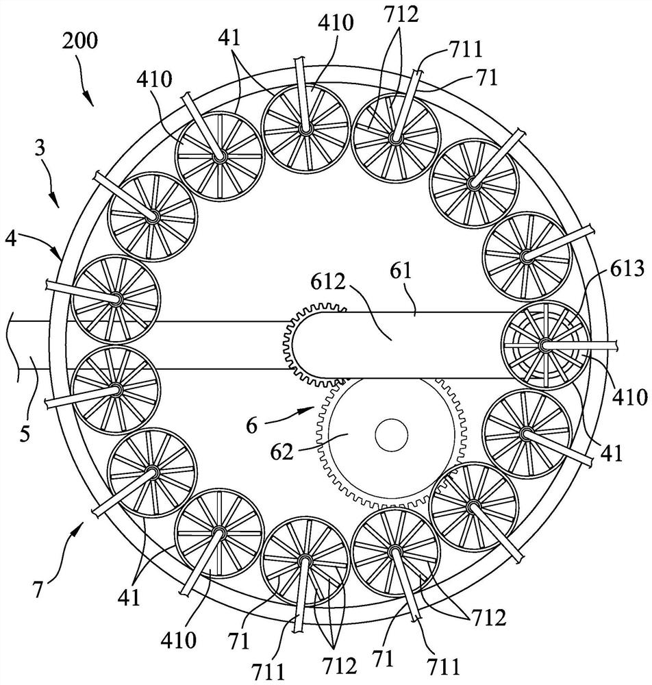
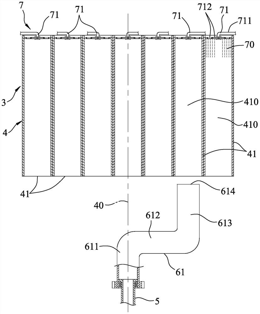
[0025] refer to figure 1 , 2 3. The first embodiment of the exhaust gas purification system 200 of the present invention is suitable for installation in an exhaust gas generating device (not shown in the figure), and can be used to purify and discharge the exhaust gas discharged from the exhaust gas generating device. The exhaust gas purification system 200 includes an exhaust gas capture mechanism 3 connected to the exhaust gas generating equipment, a purification equipment 7 installed on the exhaust gas capture mechanism 3, and a signal connection between the exhaust gas capture mechanism 3 and the purification equipment. 7 of the control device 8 (shown in Figure 4 ).

[0026] The exhaust gas capture mechanism 3 includes a circulation capture unit 4, a smoke exhaust pipe 5 connected to the exhaust gas ge...


PUM


Abstract

An exhaust gas purification system comprises an exhaust gas capture mechanism and a purification device. The exhaust gas capture mechanism comprises a circulating capturing unit and a separate injection unit, wherein the circulating capturing unit is provided with a plurality of capturing spaces communicating with the outside and used for containing exhaust gas, and the separate injection unit isused for controlling exhaust gas to be injected into the capturing spaces in turn. The purification device can be used to purify the exhaust gas in the capturing spaces. Through the structural designof the purification device and the exhaust gas capture mechanism, exhaust gas purification treatment can be more efficiently carried out in a manner of capturing exhaust gas in batches, and the exhaust gas purification system can be additionally assembled on exhaust gas generation equipment of an existing plant, so that the existing exhaust gas generation equipment and the plant structure do not need to be greatly changed and transformed; and the design of the exhaust gas purification system is quite convenient, practical and innovative.

Description

technical field [0001] The invention relates to a purification system, in particular to an exhaust gas purification system for exhaust gas. Background technique [0002] With the development of industry, high temperature treatment will be used in the processing of many materials, so many factories will set up combustion equipment to provide the required high temperature processing environment. The fuel used in such combustion equipment is usually coal or Fossil fuels, and will produce a large amount of exhaust gas, which usually contains harmful substances such as particulate pollutants, sulfur oxides, hydroxides, etc. In order to prevent the exhaust gas (smoke) generated during the operation of the combustion equipment from being directly discharged to the outside and polluting the atmospheric environment, relevant environmental protection laws and regulations have stipulated the emission standards for the exhaust gas (smoke) generated by such combustion equipment, so it is...

Claims


Application Information

Patent Timeline
IPC IPC(8): F23J15/04B01D47/06B01D53/18
CPCB01D47/06B01D53/185F23J15/04
Inventor 魏荣宗
Owner 魏荣宗
Why Eureka
Try Eureka