Printing machine paste adding device for spinning

A printing machine and pneumatic device technology, applied in printing machines, rotary printing machines, screen printing machines, etc., can solve the problems of complex overall structure, poor flexibility, and high cost, and achieve broad market prospects, low cost, and structural simple effect

Inactive Publication Date: 2017-02-01
CHANGXING COUNTY DAWEI TEXTILE CO LTD
View PDF0 Cites 1 Cited by
  • Summary
  • Abstract
  • Description
  • Claims
  • Application Information

AI Technical Summary

Problems solved by technology

[0002] In the textile process, printing is also a very important process. In the printing process, it is often necessary to add slurry. The Chinese Publication No. 204605147U is an automatic sizing device for textile flat screen printing machines, which is used for automatic sizing of textile flat screen printing machines. The device is equipped with a pneumatic pump on the flat trolley through the bracket. One end of the pneumatic pump is a slurry inlet pipe that can be connected to the slurry tank, and the outer end of the hose installed in the slurry outlet tube at the other end is installed with a slurry feeding tube through a three-way joint. The built-in circuit of the offside sensor installed near the slurry feeding pipe is connected with the solenoid valve of the pneumatic pump, and there are slurry feeding holes distributed on the slurry feeding pipe. When this design is in use, the offside sensor is adjusted by changing the slurry usage of the flat screen printing machine. The on-off pneumatic pump automatically adds slurry when the contact is offside, but the overall structure of the design is more complicated, the cost is higher, and the way of automatically adding slurry cannot meet the needs of different printings, and the flexibility is poor

Method used


Image

  • Printing machine paste adding device for spinning
  • Printing machine paste adding device for spinning

Examples


Embodiment

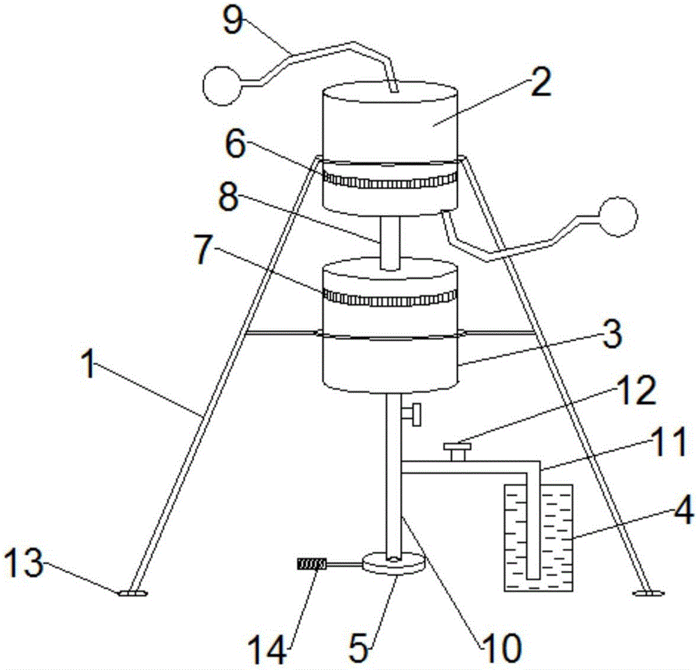
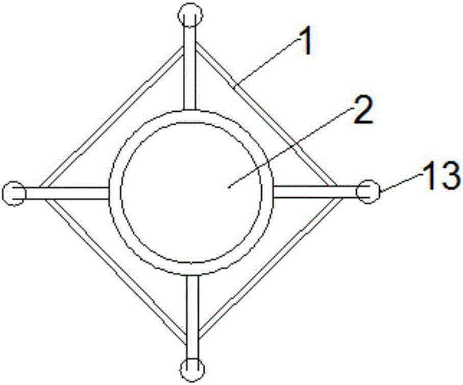
[0016] see figure 1 and figure 2 , the present invention provides a technical solution: a textile printing machine slurry adding device, including a support frame 1, an air compression cylinder 2, a slurry addition cylinder 3, a slurry storage tank 4 and a slurry tray 5, the air compression cylinder 2 and Adding slurry cylinder 3 is installed on the support frame 1, is provided with first piston 6 in described air compression cylinder 2, is provided with second piston 7 in described adding slurry cylinder 3, and described first piston 6 and the second piston 7 The bracket is provided with a propulsion rod 8, and the upper and lower ends of the air compression cylinder 2 are provided with a pneumatic device 9, and the bottom of the slurry adding cylinder 3 is connected with one end of a pulp delivery pipe 10, and the pulp delivery pipe 10 is connected with a branch pipe 11 One end, the other end of the branch pipe 11 is located in the pulp storage tank 4, the other end of the...


PUM


Abstract

The invention discloses a printing machine paste adding device for spinning. The printing machine paste adding device comprises a supporting frame, an air compression cylinder, a paste adding cylinder, a paste storage bucket and a paste disc. The air compression cylinder and the paste adding cylinder are both mounted on the supporting frame. A first piston is arranged in the air compression cylinder. A second piston is arranged in the paste adding cylinder. A first piston and second piston support is provided with a pushing rod. The upper end and the lower end of the air compression cylinder are each provided with a pneumatic device. The bottom of the paste adding cylinder is connected with one end of a paste feeding pipe. The paste feeding pipe is connected with one end of a branch pipe. The other end of the branch pipe is located in the paste storage bucket. The other end of the paste feeding pipe is connected with the paste disc. Control valves are arranged on the paste feeding pipe and the branch pipe. The printing machine paste adding device is simple and practical in overall design, simple in structure and low in manufacturing cost, the paste adding quantity can be flexibly adjusted through manual operation, and the printing machine paste adding device is suitable for some middle and small-sized enterprises, has wide market prospects and is convenient to popularize.

Description

technical field [0001] The invention relates to the field of textile equipment, in particular to a textile printing machine sizing device. Background technique [0002] In the textile process, printing is also a very important process. In the printing process, it is often necessary to add slurry. The Chinese Publication No. 204605147U is an automatic sizing device for textile flat screen printing machines, which is used for automatic sizing of textile flat screen printing machines. The device is equipped with a pneumatic pump on the flat trolley through the bracket. One end of the pneumatic pump is a slurry inlet pipe that can be connected to the slurry tank, and the outer end of the hose installed in the slurry outlet tube at the other end is installed with a slurry feeding tube through a three-way joint. The built-in circuit of the offside sensor installed near the slurry feeding pipe is connected with the solenoid valve of the pneumatic pump, and there are slurry feeding ...

Claims


Application Information

Patent Timeline
Patent Type & Authority Applications(China)
IPC IPC(8): B41F15/40
CPCB41F15/40
Inventor 臧伟
Owner CHANGXING COUNTY DAWEI TEXTILE CO LTD
Why Eureka
Try Eureka