
Diffuser device

a diffuser and nozzle technology, applied in the direction of movable spraying apparatus, burners, lighting and heating apparatus, etc., can solve the problems of accidental disengagement of the nozzle, difficulty in nozzle replacement, and inability to effectively hold the nozzle u in position, and achieve the effect of high efficiency and relatively cost-effectiv

Inactive Publication Date: 2010-01-12
KOMET AUSTRIA GMBH
View PDF11 Cites 7 Cited by
  • Summary
  • Abstract
  • Description
  • Claims
  • Application Information

AI Technical Summary

Benefits of technology

[0009]The object of the present invention is to overcome the above drawbacks, by providing a diffuser device that is highly efficient and relatively cost-effective.
[0010]A particular object is to provide a device that allows quick and easy replacement of the nozzle.
[0011]A further object is to provide a device that prevents any accidental separation between the nozzle and the support body.
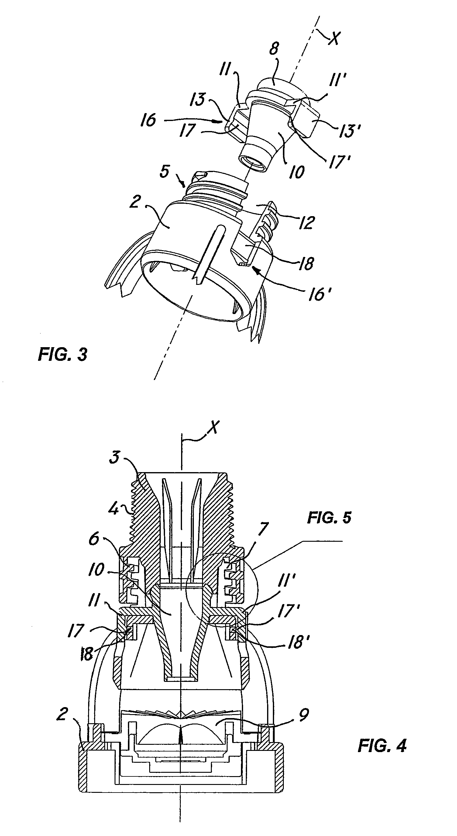
[0014]Thanks to this configuration, the device of the invention prevents any accidental separation between the nozzle and the support body as the sleeve and the body are mutually coupled. This will allow periodic replacement of the nozzle to be performed in a simple and safe manner, without causing the unsteady connection problem of prior art.

Problems solved by technology

When operating in contaminated environments, with high content of dust and earth, the recess of the snap means S fills up with foreign matter, and is no longer able to effectively hold the nozzle U in position.
As a result, undue efforts are required for removing and remounting the various parts, which makes nozzle replacement difficult.
Deterioration of the nozzle and sleeve connection also causes accidental disengagement of the nozzle.
As the sleeve is screwed onto the central body, gravity force tends to cause removal of a badly connected nozzle, which is irremediably lost in the environment.

Method used


Image

  • Diffuser device
  • Diffuser device
  • Diffuser device

Examples


Embodiment Construction

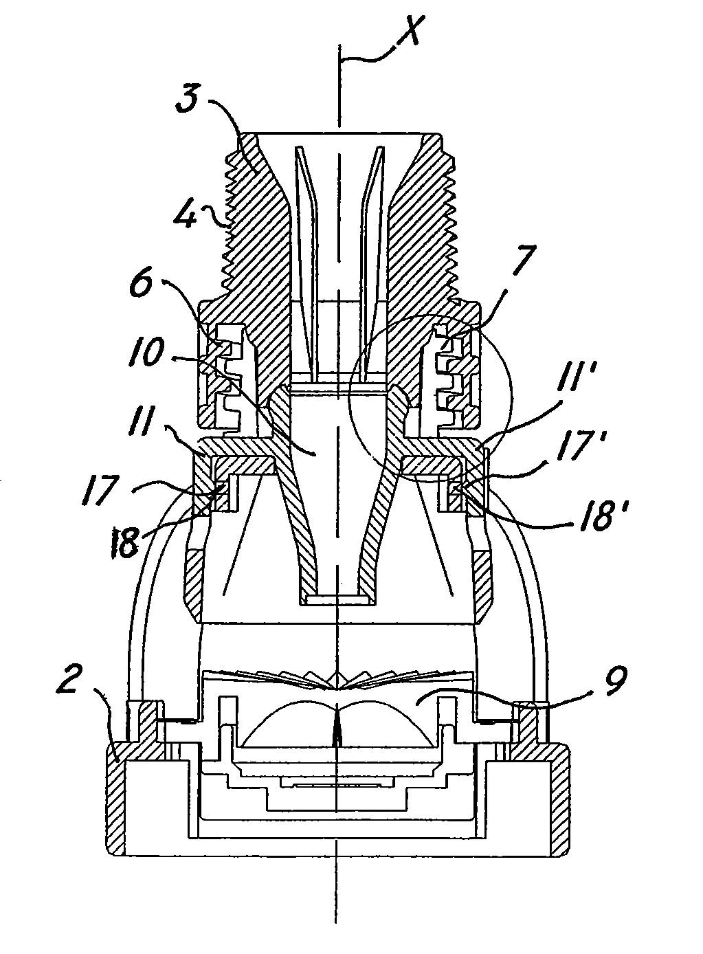
[0025]Referring to the above figures, the device of the invention, generally designated by numeral 1, may be advantageously used for irrigation systems in agriculture or other industries, e.g. in the mining industry for dust suppression and for cooling potentially self-igniting materials.

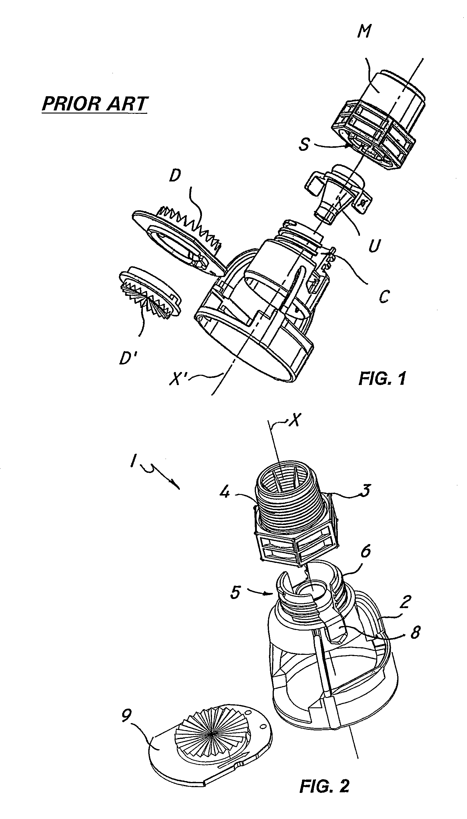
[0026]As shown in FIG. 1 and 2, the device 1 essentially comprises a partly hollow support body 2 defining a longitudinal axis X, which may be removably coupled to a sleeve 3 for connection thereof to an external liquid feed line, the latter being known per se and not shown.

[0027]To this end, the sleeve 3 has an externally threaded portion 4 for meshing with a corresponding internally threaded portion of the liquid feed line. Alternatively, the sleeve 3 may have other means for connection to the liquid feed line, such as a nut and locknut assembly or a male-female connection. Liquid from the feed line flows into the sleeve 3, which has a convergent inner profile, and is further directed downstream o...


PUM


Abstract

This invention finds application in the field of liquid distributing devices, and more particularly relates to a sprinkler head device, for example for use in sprinkler systems for distributing liquids or the like. The device comprises a support body to be removably coupled to a sleeve for connection to an external liquid supply line, a convergent nozzle between the body and the sleeve, and a diverter member downstream from the nozzle for diverting flow and sprinkling fluid out. The device further includes main connection means for removably attaching the nozzle to the support body while preventing any accidental separation thereof upon mutual coupling and uncoupling of the sleeve to the body, thereby allowing fast and easy periodic replacement of the nozzle.

Description

FIELD OF THE INVENTION[0001]This invention finds application in the field of liquid distributing devices, and particularly relates to a diffuser device, particularly for sprinkler plants for distributing liquids or similar fluids.BACKGROUND OF THE INVENTION[0002]Liquid diffuser devices are known to be particularly used in agriculture for conveying a unidirectional water flow into a nozzle and direct it to a plate which distributes it in a plurality of directions.[0003]A diffuser device head as described above is known from international application WO2004 / 050258, on which the preamble of claim 1 is based.[0004]As shown in FIG. 1, this prior art device has a partly hollow central body C, which may be connected to a liquid feed line by means of a connecting sleeve M. Liquid, whose flow direction is substantially coincident with the axis X′ of the device, passes through the sleeve M and is conveyed into a convergent nozzle U, interposed between the central body C and the sleeve M. Liqu...

Claims


Application Information

Patent Timeline
Patent Type & Authority Patents(United States)
IPC IPC(8): B05B1/26B05B3/02B05B15/65
CPCB05B1/265B05B15/065B05B15/65
Inventor DRECHSEL, ARNO
Owner KOMET AUSTRIA GMBH
Learn More