Apparatus for winding an elongate strap onto a winch

a technology of elongate straps and accessories, which is applied in the direction of mechanical equipment, lifting devices, transportation items, etc., can solve the problems of inconvenient operation, inconvenient use, and inability to wind the straps manually, etc., and achieves the effects of convenient operation, time-consuming and labor-intensive procedures, and high efficiency

Inactive Publication Date: 2010-01-12
9182 9622 QUEBEC
View PDF28 Cites 26 Cited by
  • Summary
  • Abstract
  • Description
  • Claims
  • Application Information

AI Technical Summary

Problems solved by technology

When performed in this manner, the winding tends to be carried out in an discontinuous or interrupted fashion because the user is required to constantly readjust his grip on the hub member.
The user's efforts may be further hampered by the little clearance which may exist between the hub member and the flat bed.
As a result, manual winding tends to be a highly inefficient, tedious, time-consuming and labour-intensive procedure.
Furthermore, because of the repetitive nature of the movement, the user may be at risk of developing repetitive strain disorder or other such condition.
These problems are further compounded or exacerbated in the case where this procedure needs to be repeated to effect strap winding on multiple winches.
While this crank assembly tends to constitute an improvement over manual winding of the strap onto the winch, there are concerns that the device is not sufficiently robust to resist wear arising from repeated use.
In particular, the compression member of the crank assembly may be prone to excessive wear and accordingly, may require frequent replacement.
In addition, because of its configuration, the repeated use of this device may still present some risk of injury to the user by placing undue strain on the wrist of the user.
While this device obviates the drawbacks associated with the portable crank assembly described above, its operation requires the use of two hands which may not be desirable in certain field applications.

Method used


Image

  • Apparatus for winding an elongate strap onto a winch
  • Apparatus for winding an elongate strap onto a winch
  • Apparatus for winding an elongate strap onto a winch

Examples


Embodiment Construction

[0056]The description which follows, and the embodiments described therein are provided by way of illustration of an example, or examples of particular embodiments of principles and aspects of the present invention. These examples are provided for the purposes of explanation and not of limitation, of those principles of the invention. In the description that follows, like parts are marked throughout the specification and the drawings with the same respective reference numerals.

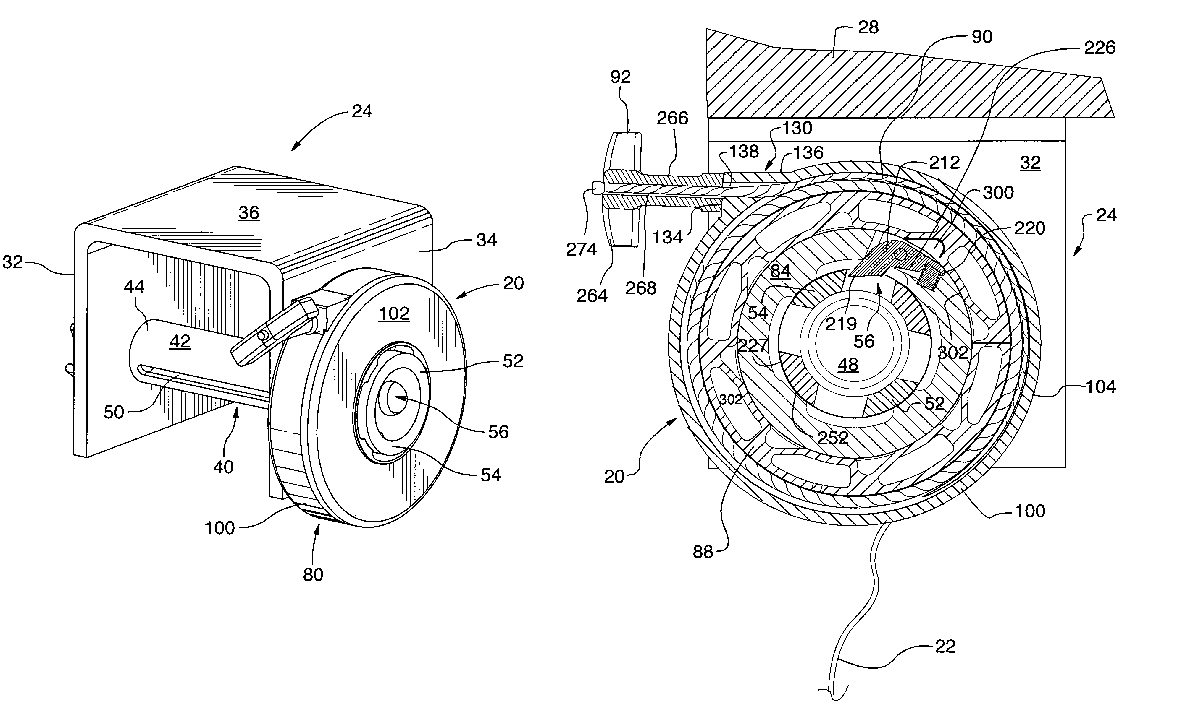
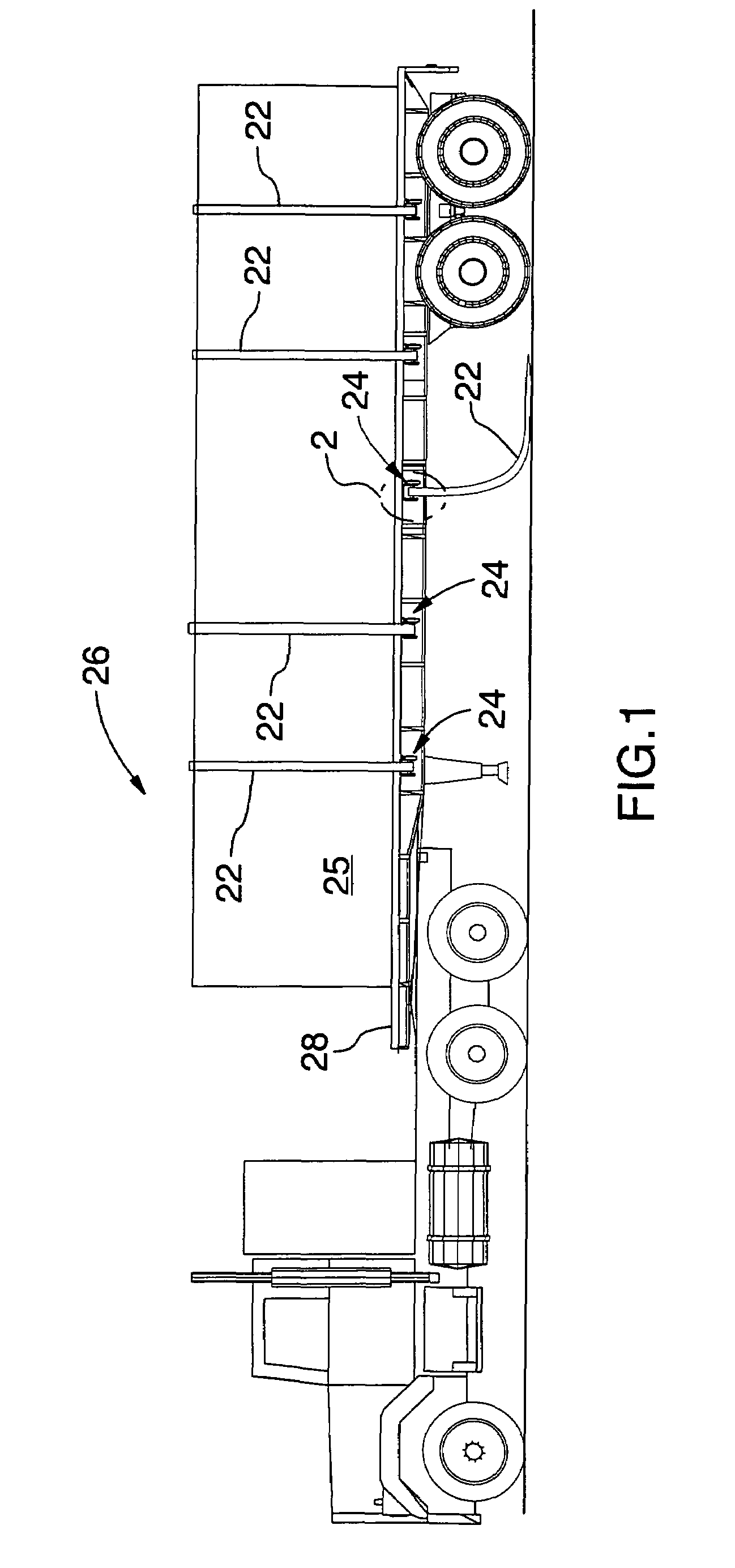
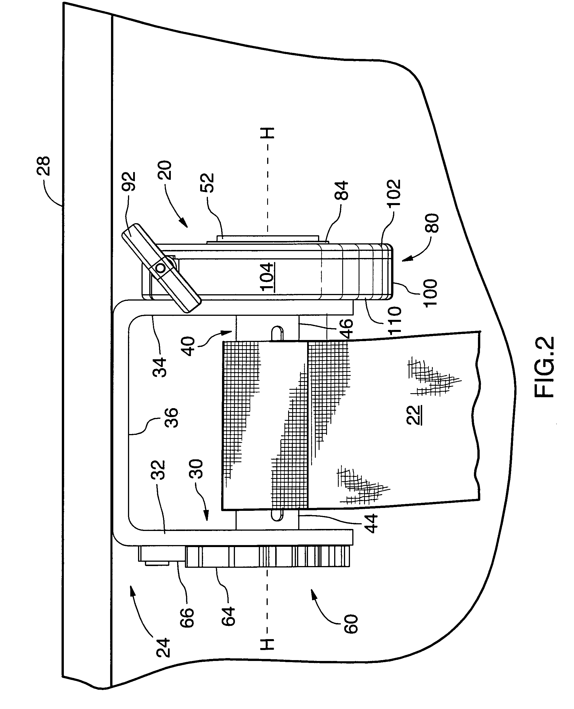
[0057]Referring to FIGS. 1, 2, 3a, 3b and 10, there is shown a strap winding apparatus designated generally with reference numeral 20. The strap winding apparatus 20 is designed to wind an elongate strap 22 onto a winch 24 when the strap 22 is not in use and needs to be safely stored. In this embodiment, the elongate strap 22 is a lading strap of the type used to restrain and / or secure cargo 25 onto a support surface. However, it will be appreciated that the strap winding apparatus 20 is not limited to applica...


PUM

PropertyMeasurementUnit
lengthaaaaaaaaaa
lengthaaaaaaaaaa
spring energyaaaaaaaaaa

Abstract

The present invention relates to an apparatus for winding an elongate strap onto a winch. The winch has a hub member to which may be coupled the strap winding apparatus and a reel element fixed to the hub member about which may be wound the elongate strap. The strap winding apparatus has a protective housing and a winding assembly at least partially retained within the housing. The winding assembly includes a coupling ring sized to fit over the hub member for selective mating therewith and a spool assembly. The spool assembly has a spool member mounted in surrounding relation with the coupling ring, a cord which may be wound about the spool member and which may be pulled to urge rotation of the spool member in a first direction, and a torsion spring member connected to both the housing and the spool member. The spring member is configured to store spring energy when the cord is pulled and the spool member rotates in the first direction, and to release spring energy to the spool member when the cord is released thereby urging the spool member to rotate in a second direction opposite to the first direction and causing the cord to be wound about the spool member. The coupling ring has an engagement member pivotally mounted thereto. The engagement member is engageable with both the hub member and the spool member so as to allow torque from the spool member to be transmitted to the hub member via the coupling ring such that when the cord is pulled and the spool member rotates in the first direction the hub member will also rotate thereby causing the elongate strap to be wound about the reel member. The apparatus may be also be used to wind other elongate flexible elements such as webbing, a rope, a cable or a cord.

Description

FIELD OF THE INVENTION[0001]The present invention relates to an apparatus for winding an elongate strap or other flexible element onto a winch.BACKGROUND OF THE INVENTION[0002]Flat bed trailers have been used increasingly to transport timber, lumber, metal stock, machinery and other cargo. The cargo is usually secured to the flat bed using long flexible straps carried on winches mounted to the underside of the flat bed. In a typical cargo securing operation, a suitable length of strap is drawn from the winch, placed across the top of the cargo and attached to both sides of the flat bed.[0003]Once the cargo is removed from the flat bed, it becomes necessary to rewind the length of strap onto the winch for safe storage. This task is often performed by manually rotating the hub member which projects from the side of the winch bracket. More specifically, the operator or user grasps the hub member and turns the hub member manually in angular increments in the winch take-up direction to e...

Claims


Application Information

Patent Timeline
Patent Type & Authority Patents(United States)
IPC IPC(8): B21F9/00
CPCB60P7/0846B65H54/585
Inventor RODRIGUE, MARQUIS
Owner 9182 9622 QUEBEC
Why Eureka
Try Eureka