Push nut

a technology of push nuts and nut ends, which is applied in the direction of threaded fasteners, fastening means, mechanical devices, etc., can solve the problems of difficult work, low material yield, and hardly conducted press molding, so as to reduce the resistance of insertion onto the bolt, prevent insertion of the insertion of the insertion, and enhance the elastic force of the engaging piece

Inactive Publication Date: 2010-01-12
PIOLAX CO LTD
View PDF14 Cites 16 Cited by
  • Summary
  • Abstract
  • Description
  • Claims
  • Application Information

AI Technical Summary

Benefits of technology

[0009]The present invention has been made in view of the above circumstances and provides a push nut. According to one aspect of the invention, a push nut can be easily inserted onto a bolt, and the inserting work of the push nut can be done while the nut is pressed by two fingers, and the material yield of the push nut is high.
[0011]According to the above configuration, a tip end portion of the bolt is inserted into the bolt passing hole of the base plate from the lower face side that is not in the direction along which the engaging pieces are folded back, and the push nut is pressed toward the base end of the bolt while the engaging pieces of the push nut are pressed by fingers. Then, the tip end portions of the four engaging pieces move toward a base end of the bolt while overriding the thread of the bolt, and, at positions where the base plate is in contact with an attached member, the tip end portions of the engaging pieces engage with a thread groove of the bolt to perform locking. In this case, a required locking force is ensured by the coupling forces of the four engaging pieces. Therefore, the widths of the engaging pieces can be reduced, and the insertion force to be applied on the bolt can be reduced to a relatively small degree. In the process of pushing onto the bolt, the push nut hardly inclines with respect to the bolt. Even when the push nut inclines with respect to the bolt, the case where insertion is disabled does not occur. Therefore, the workability of attachment can be improved. Two of the engaging pieces extend from each of the pair of opposing sides of the base plate. Therefore, the push nut can be pushed by two fingers while two engaging pieces are simultaneously pressed by one of the fingers, and the push nut can be easily attached even in the case where the attachment work is conducted in a space where only the index and mid fingers can reach the engaging pieces. Since two of engaging pieces extend from each of the pair of opposing sides of the base plate, the shape in a developed state can be compact, and the material yield of the production process can be improved.
[0013]According to the above configuration, when pressed by fingers, the engaging piece of which the tip end portion is narrowed bends more flexibly, and moves more downward. As a result, when the engaging pieces are pushed maximumly, adjacent engaging pieces stop at different levels. By contrast, the thread groove in the outer circumference of the bolt is spiral, and hence the height of the thread is varied when the circumferential position is changed. When all the tip end portions of the engaging pieces are at the same level, therefore, the tip end portion of one of the engaging pieces overrides the thread. When adjacent engaging pieces stop at different levels as described above, however, each of the engaging pieces can engage with the thread groove, and rattling can be effectively prevented. The insertion resistances of the two engaging pieces are reduced, and therefore also the whole insertion resistance is reduced. Consequently, the insertion property can be improved.
[0015]According to the above configuration, the engaging piece in which the angle of inclination of the tip end portion is small has a lower insertion resistance, and hence is pushed more inwardly. Therefore, adjacent engaging pieces stop at different levels. As a result, for the same reason as described above, each of the engaging pieces can engage with the thread groove, and rattling can be effectively prevented. The insertion resistances of the two engaging pieces are reduced, and therefore also the whole insertion resistance is reduced. Consequently, the insertion property can be improved.
[0017]According to the above configuration, in each of the engaging pieces, the length between a portion coupled to the base plate and the tip end portion can be increased as far as possible. Then the elastic force of the engaging piece can be enhanced. Therefore, the resistance of insertion onto the bolt can be reduced. Moreover, the base portions of two engaging pieces which extend from the same side of the base plate can be made close to each other, and hence it is easy to simultaneously press the two engaging pieces by one finger. Furthermore, the tip end portions of the four engaging pieces can be placed so as to evenly surround the periphery of the bolt passing hole. Therefore, the insertion resistance during insertion onto the bolt can be prevented from being biased, and the push nut can be prevented as far as possible from inclining in the process of being inserted.
[0018]As described above, according to a further aspect of the invention, the insertion force to be applied on the bolt can be reduced to a relatively small degree. On the way to push onto the bolt, the push nut hardly inclines with respect to the bolt. Even when the push nut inclines with respect to the bolt, the case where insertion is disabled does not occur. Therefore, the workability of attachment can be improved. Two of the engaging pieces extend from each of the pair of opposing sides of the base plate. Therefore, the push nut can be pushed by two fingers while two engaging pieces are simultaneously pressed by one of the fingers, and the push nut can be easily attached even in the case where the attachment work is conducted in a space where only the index and mid fingers can reach the engaging pieces. Since the shape in a developed state can be compact, the material yield of the production process can be improved.

Problems solved by technology

Furthermore, there is a case where one of the engaging pieces fails to engage with the thread groove although the other engaging piece engages with the thread groove, thereby causing rattling.
The push nut of EP1182369A2 above has a problem in that, during production, the engaging pieces must be bent respectively in three directions, and hence press molding is hardly conducted.
The push nut has another problem in that, in a developed state, it has a shape in which the engaging pieces radially extend from the outer circumference of the base plate, and hence material yield is low.
In a narrow space where a hand can be inserted but only the index and mid fingers can reach the engaging pieces, therefore, it is sometimes difficult to work.

Method used


Image

  • Push nut
  • Push nut
  • Push nut

Examples


Embodiment Construction

[0028]Hereinafter, an embodiment of the invention will be described with reference to the drawings.

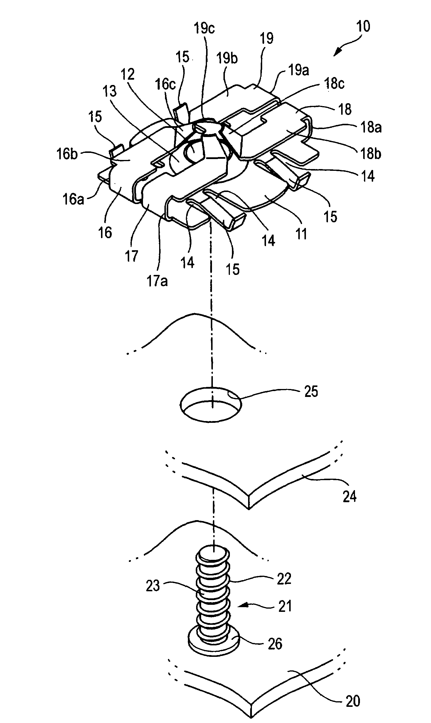
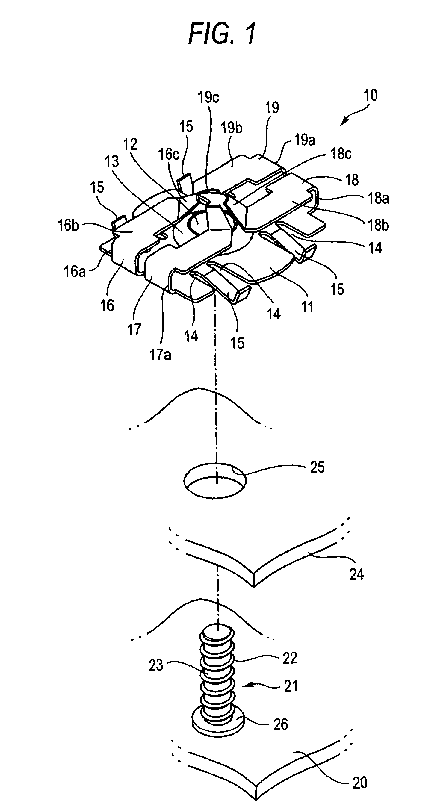
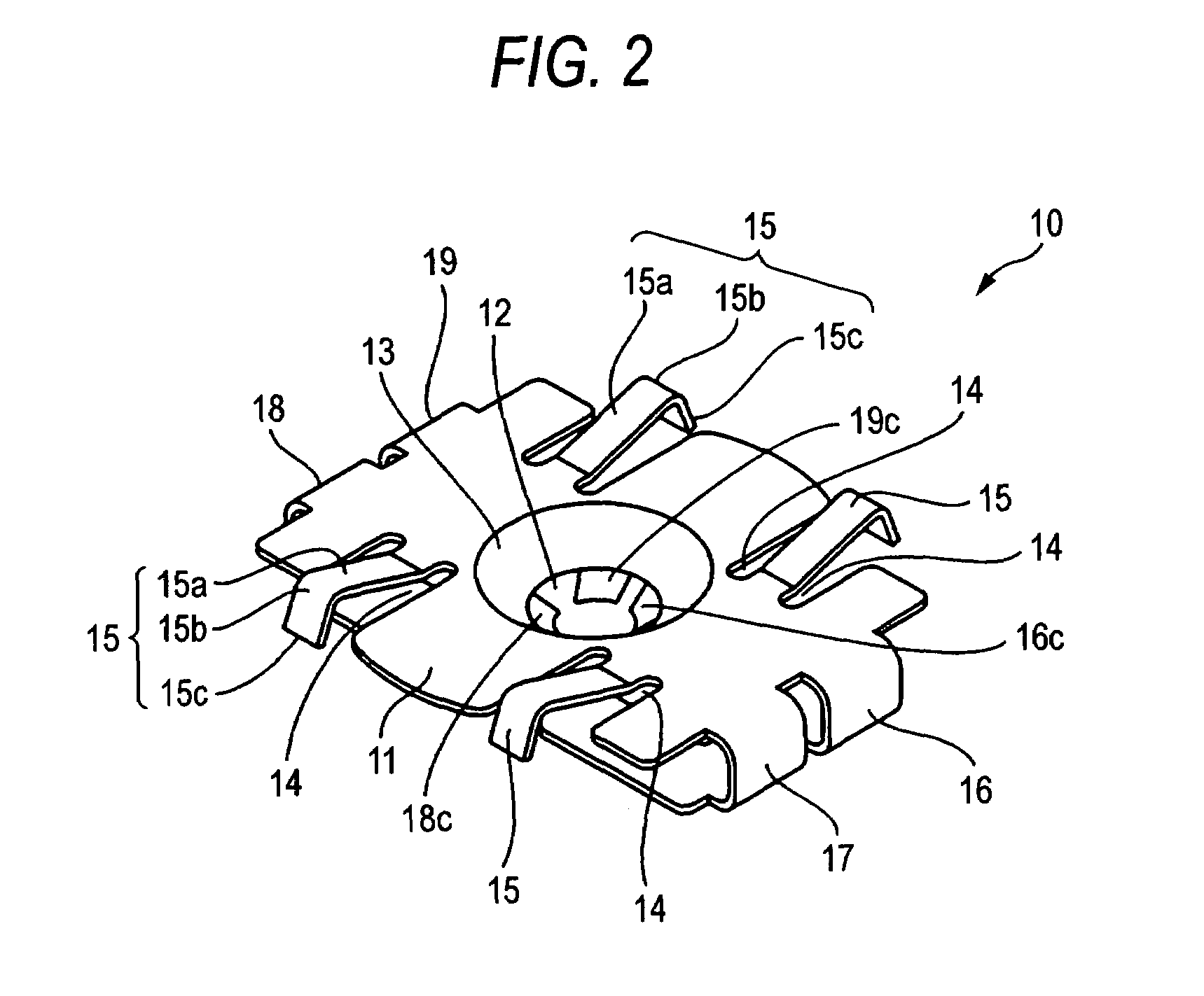
[0029]FIG. 1 is a perspective view showing a state where an attached plate is attached to a panel using a push nut which is an embodiment of the invention. FIG. 2 is a perspective view of the push nut as viewed from the side of the lower face. FIG. 3A is a front view of the push nut, and FIG. 3B is a rear view of the push nut. FIG. 4A is a plan view of the push nut, and FIG. 4B is a bottom view of the push nut. FIG. 5A is a right side view of the push nut, and FIG. 5B is a left side view of the push nut.

[0030]FIG. 6A is an end view of the push nut taken along the arrow line A-A of FIG. 3A, and FIG. 6B is an end view of the push nut taken along the arrow line B-B of FIG. 3A. FIGS. 7A and 7B are views illustrating a state where the attached plate is to be fixed to the panel using the push nut. FIG. 8 is a section view showing a state where the attached plate is fixed to the panel using t...


PUM


Abstract

A push nut including a base plate formed with a bolt passing hole at a center of the base plate and four engaging pieces. Pairs of engaging pieces extend respectively from a pair of opposing sides of the base plate, base portions of the four engaging pieces are folded back to have a U-shape, and tip end portions of the engaging pieces extend to a surrounding of the bolt passing hole. The tip end portions of the four engaging pieces surround a periphery of the bolt passing hole. The four engaging pieces incline toward an insertion direction of a bolt and elastically abut against an outer circumference of the bolt, which is inserted into the bolt passing hole.

Description

BACKGROUND OF THE INVENTION[0001]1. Field of the Invention[0002]The present invention relates to a push nut which is caused to engage with a thread groove of a bolt simply by being pushed onto the bolt, and which functions as a nut.[0003]2. Description of the Related Art[0004]A push nut which can be fixed simply by pushing onto a bolt does not require a tool such as a wrench, and has good attachment workability. Therefore, a push nut is used as means for attaching a part of an automobile or the like, and particularly suitable for use in the case where a work of attaching a part must be gropingly conducted while inserting a hand into a narrow space.[0005]EP 0750122A1 discloses a push nut including: a base plate in which a bolt passing hole is disposed in a center portion; and two engaging pieces which extend from a pair of opposing sides of the base plate, respectively. In the engaging pieces, base portions are folded back into a U-shape, and tip end portions extend to a surrounding ...

Claims


Application Information

Patent Timeline
Patent Type & Authority Patents(United States)
IPC IPC(8): F16B37/16F16B21/18
CPCF16B37/0857
Inventor YONEOKA, AKIRA
Owner PIOLAX CO LTD
Why Eureka
Try Eureka