Viscous medium feeder

a feeder and viscous medium technology, applied in the direction of liquid fuel engines, movable measuring chambers, instruments, etc., can solve the problems of introducing an undesired problem, difficulty in obtaining an equal droplet size, and difficulty in high-precision screw manufacturing, etc., to achieve good sealing properties and sufficient flexibility

Inactive Publication Date: 2010-01-19
MYDATA AUTOMATION
View PDF16 Cites 6 Cited by
  • Summary
  • Abstract
  • Description
  • Claims
  • Application Information

AI Technical Summary

Benefits of technology

[0012]By providing the tubular portion with one or more internal threads, the above-mentioned problems of the prior art O-rings are eliminated while an advantage of the prior art extruder feeder is retained. The / each internal thread embodies a distinct and continuous canal wherein the viscous medium is easily forced ahead.
[0021]In one embodiment of the feeder tube, at least a substantial portion thereof has a non-circular outer shape. This, inter alia, is advantageous compared to the prior art stack of O-rings, since the non-circular shape at least substantially prevents rotation of the feeder tube. The O-rings, on the other hand, are not locked to the same extent, which could lead to a situation, where the O-rings are caused to rotate along with the screw. This would lead to a reduced output of viscous medium from the feeder.

Problems solved by technology

However, due to small dimensions, the screw is difficult to manufacture with high precision, and the stack of O-rings, while providing a good flexible seal towards the thread of the screw, is not optimal as regards the transport of the medium through the feeder, since some amounts of the medium tend to get stuck at a bottom area of the narrow recesses formed between adjacent O-rings.
The gap is necessary in order to keep the heat increase due to friction on an acceptable level, but results in a problem of leakage when it comes to the viscous mediums that are used in a jetting device.
If the principle structure of the prior art extruder feeder would be applied to a feeder of a jetting device, there would be a problem of obtaining an equal droplet size.
Due to the small dimensions of the feeder and small volume of each droplet, an arbitrary or not fully controllable variation of the droplet size introduces an undesired problem.
In addition, it would not be possible to eliminate the gap, since then the shaft would not be rotatable.

Method used


Image

  • Viscous medium feeder
  • Viscous medium feeder
  • Viscous medium feeder

Examples


Embodiment Construction

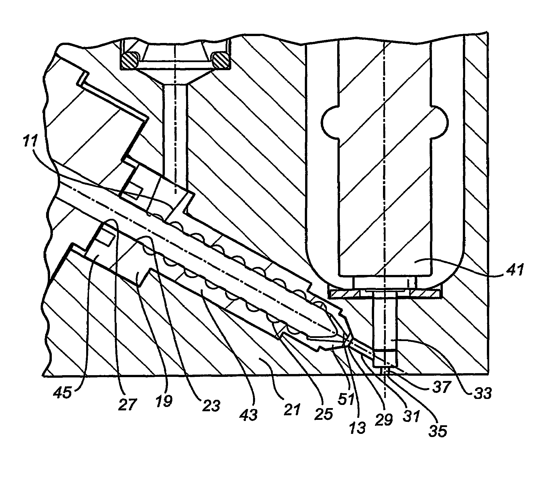
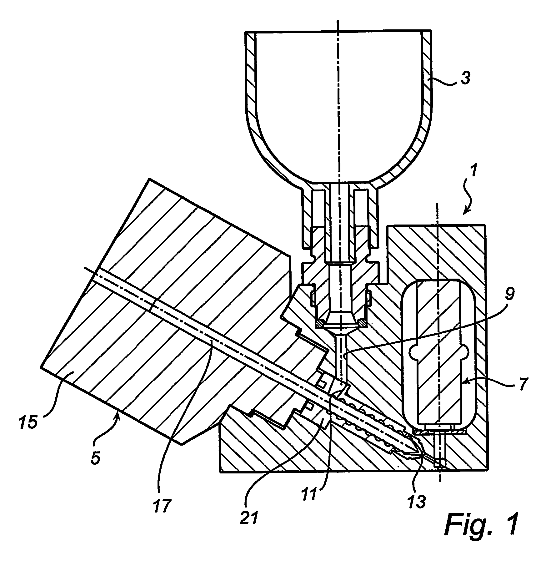
[0029]In the following, the invention will be explained in a jetting device application. However, it is to be noted that the invention will also be applicable to other types of devices comprising a viscous medium feeder. As shown in FIG. 1, a typical jetting device 1 comprises a viscous medium container 3, a feeder mechanism 5 and an eject mechanism 7. A medium channel 9 connects the medium container 3 with an inlet 11 of the feeder 5, and an outlet 13 of the feeder 5 is connected with the eject mechanism 7. More particularly, the feeder 5 comprises a drive motor 15, a shaft 17 connected to the motor 15, and a feeder tube 19 mounted in a boring of a body 21 of the device. The shaft 17 is introduced into the feeder tube 19.

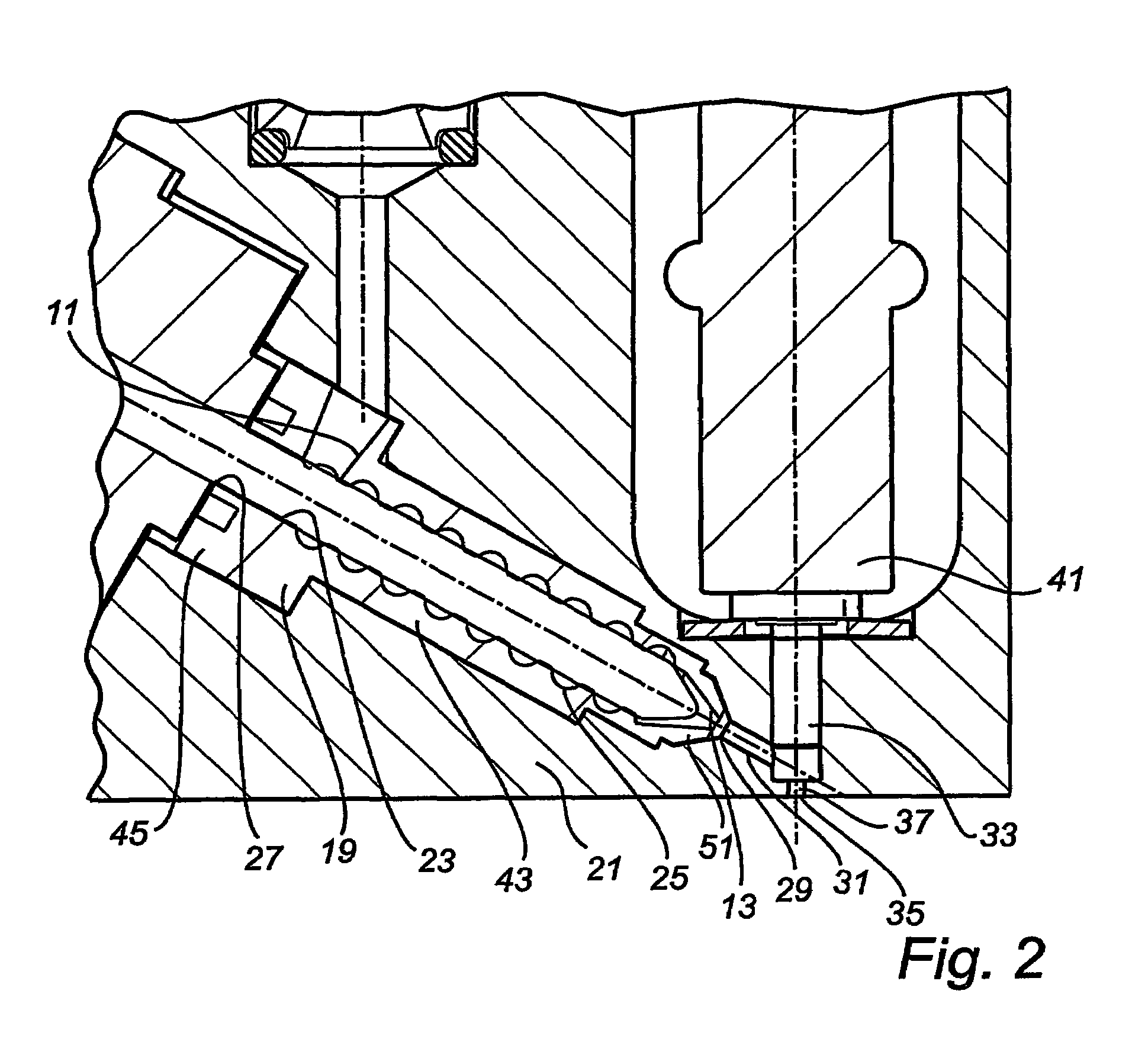
[0030]As shown in greater detail in FIGS. 2-5, the feeder tube 19 has a tubular portion 23, which is a longitudinal through hole. The center axis of the tubular portion 23 coincides with the longitudinal axis of the feeder tube 19. The inlet 11 is formed close to o...


PUM

PropertyMeasurementUnit
viscousaaaaaaaaaa
constant radiusaaaaaaaaaa
diameteraaaaaaaaaa

Abstract

A viscous medium feeder, which has an inlet, an outlet, a tubular portion, a rotatable cylindrical shaft arranged in and extending coaxially with the tubular portion, and a drive motor connected to the shaft. The tubular portion has an internal thread, which is connected, at one end thereof, to the inlet, and, at the other end thereof, to the outlet. Further, the tubular portion is elastic, and the shaft abuts the inner wall portions of the tubular portion.

Description

TECHNICAL FIELD[0001]This invention relates generally to the field of feeding viscous mediums, and in particular it relates to feeding the viscous medium within a jetting device.TECHNICAL BACKGROUND[0002]In a jetting device the medium to be jetted is first transported, or fed, to a chamber, and then ejected from the chamber through a nozzle. Thus a droplet of the medium leaves the device and, typically, impacts a closely arranged surface and thereby forms a dot on the surface. The operation of feeding the medium to the chamber is of great influence for the performance of the device, for example as regards the jetted amount, i.e. the volume of the droplet.[0003]A prior art device showing an overall good performance is disclosed in WO 99 / 64167, where the principal parts of the feeder are a tubular portion defined by a plurality of O-rings, which are disposed in a cylindrical boring, and which are stacked on top of each other; and a threaded shaft that extends through the tubular porti...

Claims


Application Information

Patent Timeline
Patent Type & Authority Patents(United States)
IPC IPC(8): B05C5/02B29C47/66B05C5/00B05C11/10B29C48/03B29C48/27B29C48/68
CPCB05C5/02B05C11/10B29C47/0818B29C47/0877B29C47/66B29C47/0009B29K2819/00B29C48/03B29C48/256B29C48/27B29C48/68
Inventor HOLM, WILLIAMNILSSON, KENTHSVALLING, PETER
Owner MYDATA AUTOMATION
Why Eureka
Try Eureka