Eureka AIR delivers breakthrough ideas for toughest innovation challenges, trusted by R&D personnel around the world.

Control system including two control columns that are coupled to enable controlled members to be placed in required positions

a control system and control column technology, applied in mechanical control devices, manual control with single control member, actuation personally, etc., can solve the problems of serious safety compromising, resisting force cannot be applied to the control column, and the movement coordination of the two control columns is compromised

Active Publication Date: 2010-01-19
DASSAULT AVIATION
View PDF6 Cites 33 Cited by
  • Summary
  • Abstract
  • Description
  • Claims
  • Application Information

AI Technical Summary

Benefits of technology

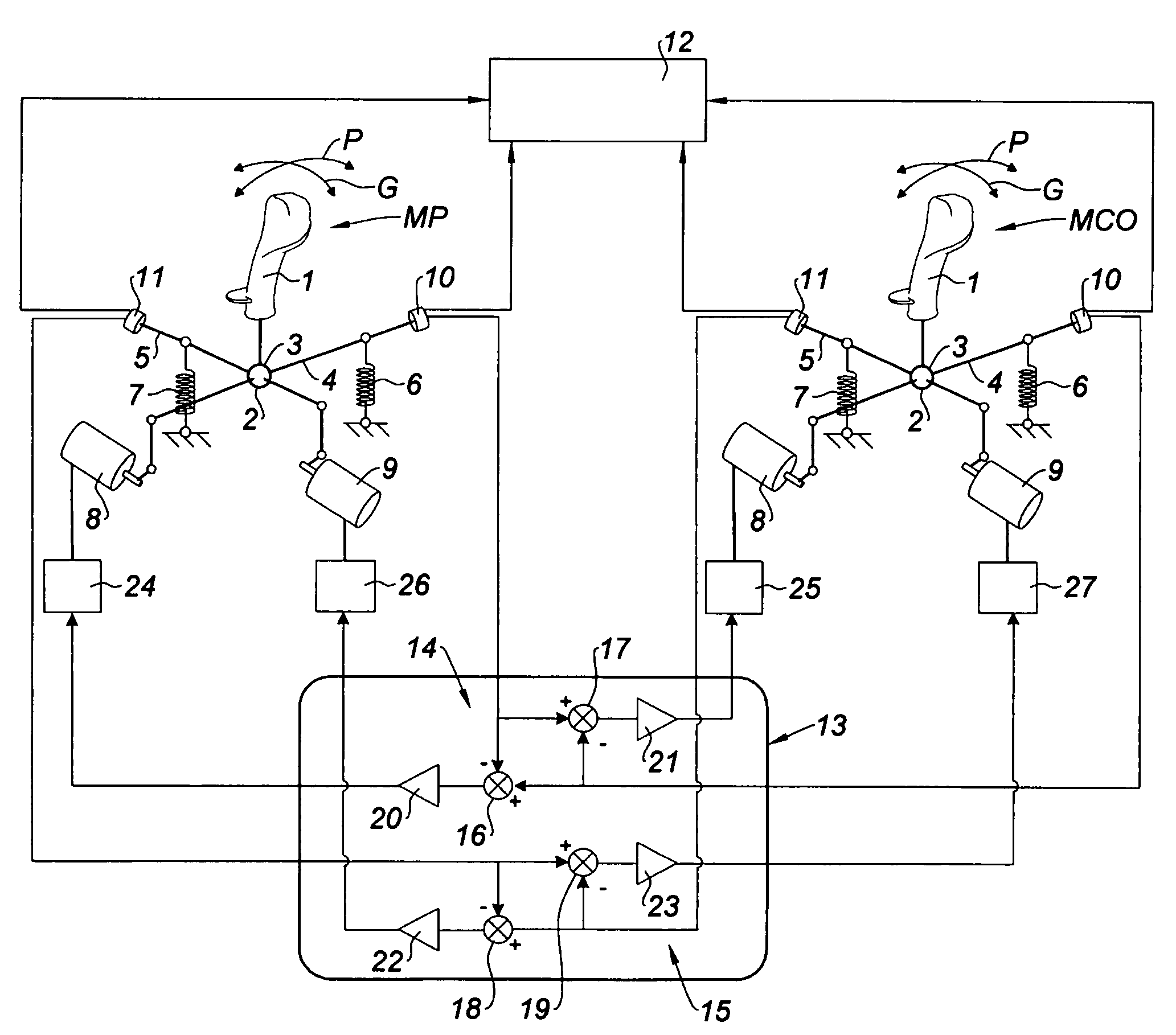
[0017]The invention therefore provides a decisive advantage over the prior art, in particular in the avionics field, because the members to be moved, to be more precise the pitch and roll control surfaces, can still be operated in complete safety in the event of an electrical failure of the control system, with slightly reduced resisting forces supplied exclusively by the mechanical spring systems.
[0028]It may also be advantageous if each of said control loops includes electronic filters to produce a damping effect in the control of the movements of the control columns.

Problems solved by technology

Consequently, in the event of a failure in the control system, in particular an electrical failure, not only is the coordination of the movement of the two control columns compromised but also the resisting forces can no longer be applied to the control columns, which seriously compromises safety, and is unacceptable in many situations and in particular in the field of avionics.

Method used


Image

  • Control system including two control columns that are coupled to enable controlled members to be placed in required positions
  • Control system including two control columns that are coupled to enable controlled members to be placed in required positions
  • Control system including two control columns that are coupled to enable controlled members to be placed in required positions

Examples


Embodiment Construction

[0041]Further scope of applicability of the present invention will become apparent from the detailed description given hereinafter. However, it should be understood that the detailed description and specific examples, while indicating preferred embodiments of the invention, are given by way of illustration only, since various changes and modifications within the spirit and scope of the invention will become apparent to those skilled in the art from this detailed description.

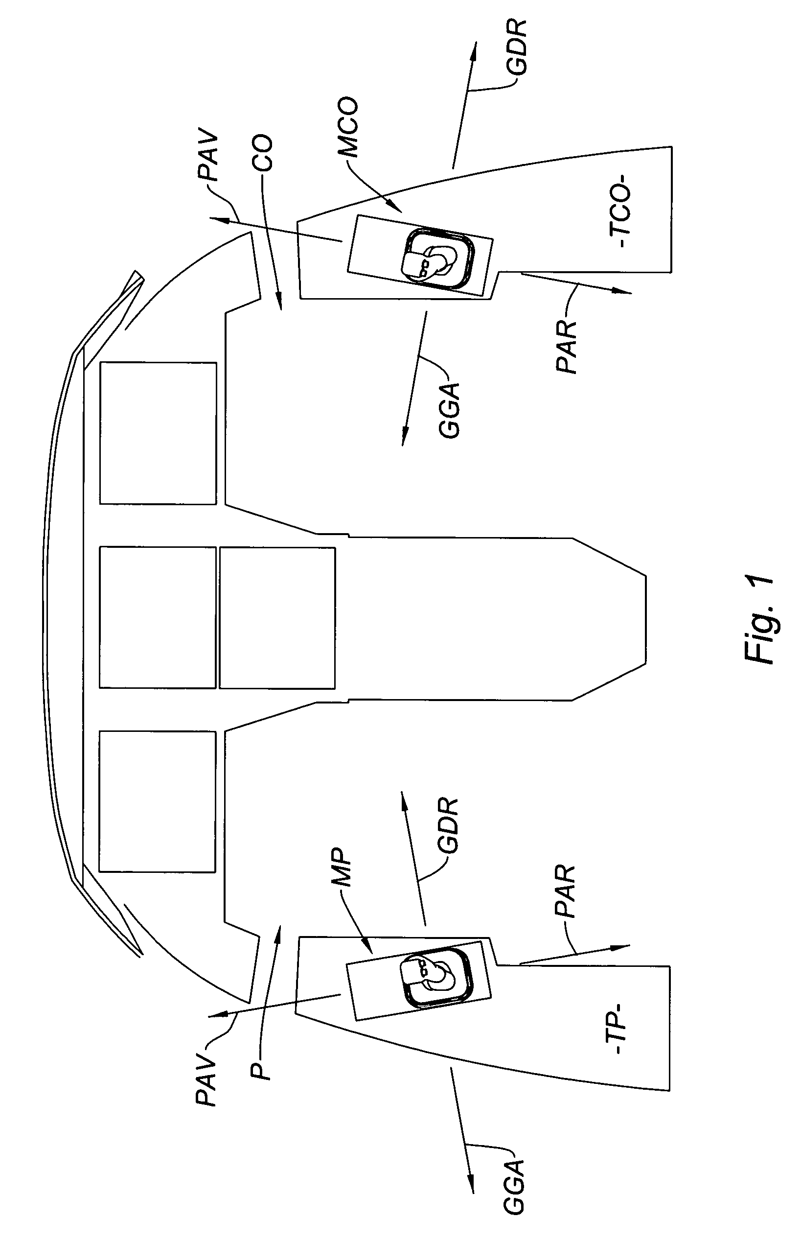
[0042]The invention is described hereinafter in its application to controlling the roll and pitch control surfaces of an aircraft, in which case the controlled members are the ailerons and the pitch control surface of the aircraft.

[0043]Note, however, that the invention may be applied to other types of controlled member where dual control applies, whether in the field of avionics or in other technical fields.

[0044]This being the case, FIG. 1 represents one example of the layout of the pitch and roll axis control ...


PUM


Abstract

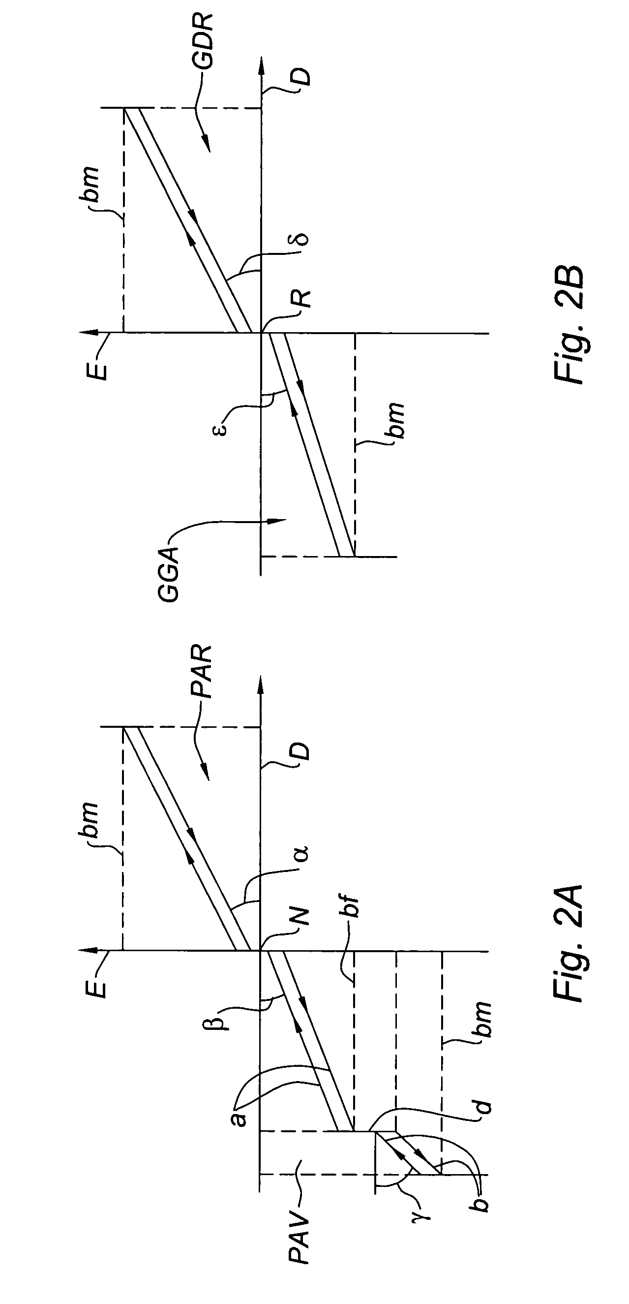
A control system for placing controlled members in required positions including two control columns assigned to the controlled members to be moved, each control column having two degrees of freedom. Two actuators controlled by two control circuits apply to their associated control column either a resisting torque or a displacement torque. Each control column is provided with a mechanical spring system spring-loading the associated control column into its neutral position and adapted to provide, in the event of manipulation of the corresponding control column, a resisting torque in support of the resisting torque supplied by the associated actuator.

Description

BACKGROUND OF THE INVENTION[0001]The present invention relates to a control system including two control columns that are coupled to enable controlled members to be placed in required positions.[0002]The invention relates more particularly, although not exclusively, to the application of a control system of the above kind to positioning the control surfaces—in particular the pitch and roll control surfaces—of an aircraft having a cockpit with dual controls.[0003]The document U.S. Pat. No. 5,291,113 discloses an aircraft control system of the above type comprising two control columns, each of which is mounted on a gimbal and has two degrees of freedom assigned to the respective controlled members to be moved, and, for each of said control columns, and assigned to said respective degrees of freedom:[0004]a) two actuators for applying to their associated control column either a resisting torque or a displacement torque for the associated degree of freedom,[0005]b) two control circuits ...

Claims


Application Information

Patent Timeline
Patent Type & Authority Patents(United States)
IPC IPC(8): B64C13/12
CPCB64C13/04B64C13/12G05G9/047G05G11/00G05G2009/04718G05G2009/04766B64C13/0421G05D1/0055
Inventor GRANIER, ERICGUERARD, JEREMIEVIET, MAX-MAURICE
Owner DASSAULT AVIATION
Why Eureka
Eureka Blog
Learn More