Mechanism for fastening casing into wall opening

a technology of casing and wall opening, which is applied in the direction of instruments, furniture parts, machine supports, etc., can solve the problems of slowing down the mounting of the plug-in unit assembly and being more complicated, and achieve the effect of speeding up the mounting of the casing

Active Publication Date: 2010-01-19
ABB (SCHWEIZ) AG
View PDF8 Cites 2 Cited by
  • Summary
  • Abstract
  • Description
  • Claims
  • Application Information

AI Technical Summary

Benefits of technology

[0007]The invention is based on providing a pressing element that can be moved in the longitudinal direction of the casing and rotated about its axis of rotation between a normal position and a mounting position, whereby the pressing element, when in its normal position, is capable of coming into contact with the other side of the wall in order to achieve a force keeping the casing in place and, when in its mounting position, the pressing element allows the casing to be pushed into the final mounting depth thereof.
[0008]An advantage of the fastening mechanism of the invention is that all measures needed for mounting the casing can be carried out on the same side of the wall where the casing is to be mounted to. In addition, a casing provided with the fastening mechanism of the invention can be implemented such that all the mounting accessories are integrated into the casing and thus cannot come loose and be lost. Due to the above characteristics, the fastening mechanism of the invention may also speed up the mounting of the casing to the wall.

Problems solved by technology

A problem with the prior art mechanisms for fastening plug-in units is that the mounting of the plug-in unit assembly requires working on both sides of the wall to which the unit is to be mounted.
Moreover, different loose accessories are needed in the mounting, which further slows down the mounting of the plug-in unit assembly and makes it more complicated.

Method used


Image

  • Mechanism for fastening casing into wall opening
  • Mechanism for fastening casing into wall opening

Examples


Embodiment Construction

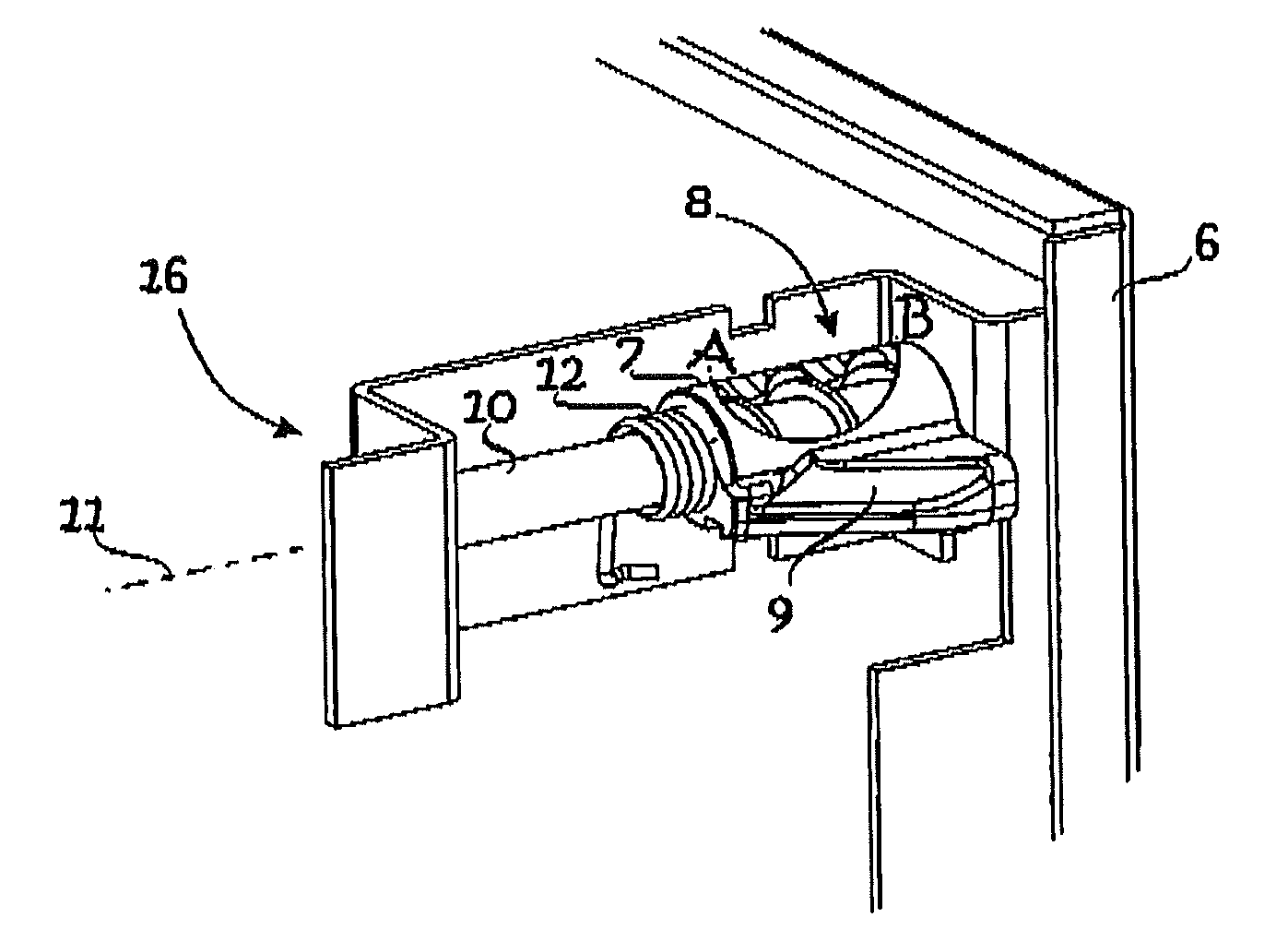
[0012]The fastening mechanism of FIG. 1 comprises a pressing element 8, a screw means 10, a spring means 12 coupled to the pressing element 8, and a collar means 6. The pressing means 8 is capable of rotating about its axis of rotation 11 between a normal position and a mounting position. If the pressing element 8 is deviated to the mounting direction, the spring means 12, which in the mechanism of FIG. 1 is a torsion spring, tends to return the element back to its normal position.

[0013]In FIG. 1 the pressing element 8 is in its normal position. It is also in its extreme position, in which its distance from the collar element 6 is at the minimum.

[0014]In the fastening mechanism of FIG. 1 the pressing element 8 and the spring means 12 are mounted coaxially with the screw means 10, i.e. the screw means goes through these components. In addition to a body 7 on top of the screw means 10, the pressing element 8 comprises a beveled guide part 9.

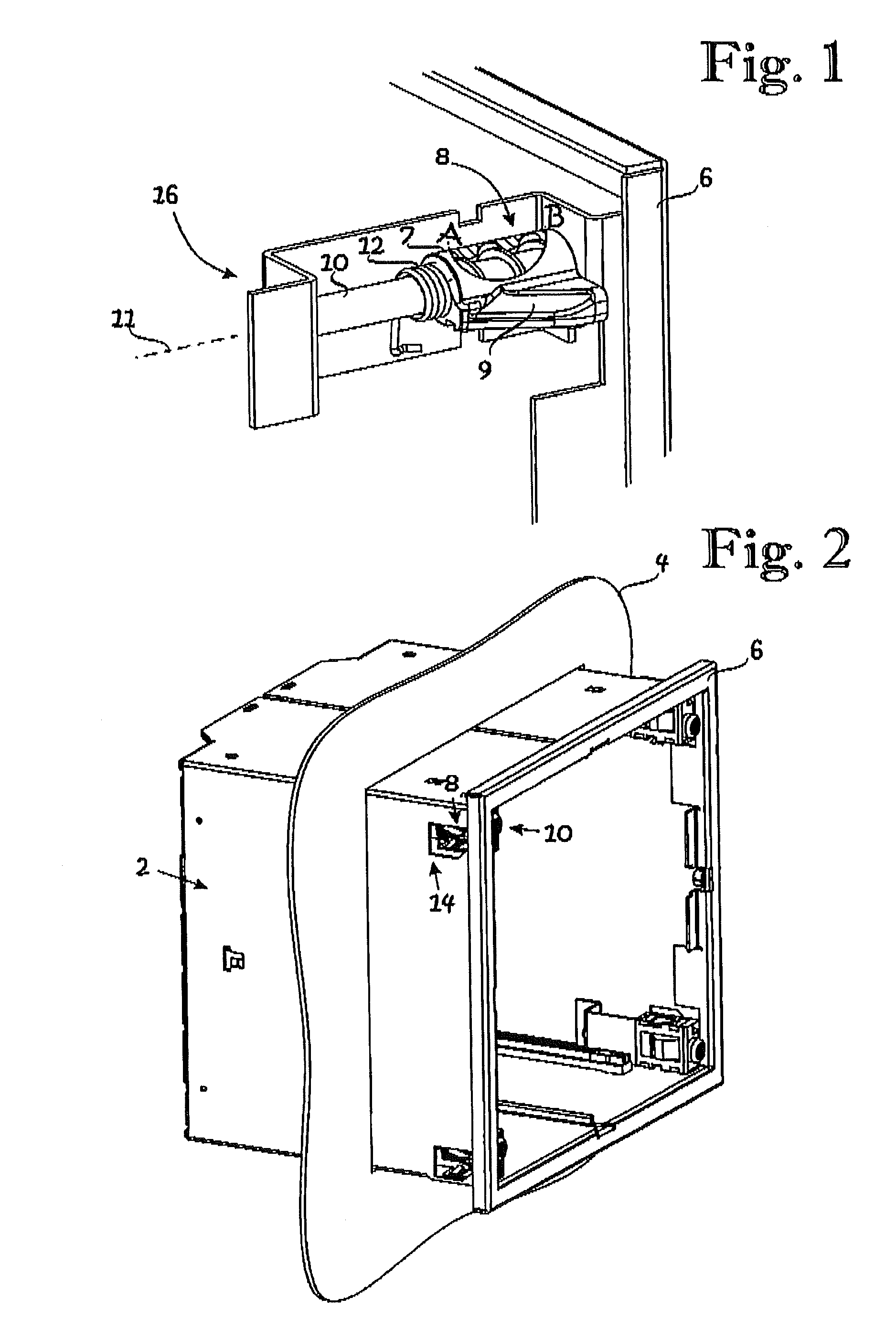
[0015]FIG. 2 illustrates the mounting of a c...


PUM


Abstract

A fastening mechanism for fastening a casing (2) into an opening in a wall (4), the mechanism comprising a collar element (6) fastened to the casing and arranged to be in contact with a first side of the wall, a pressing element (8) arranged to be in contact with a second side of the wall, the collar element and the pressing element being arranged to co-operate to direct a pressing force towards the w all, and a screw means (10) arranged to move the pressing element. The pressing element is arranged to rotate between a normal position and a mounting position; in the normal position the pressing element is capable of coming into contact with the second side of the wall to achieve a force keeping the casing (2) in place and in the mounting position it allows the casing to be pushed into the final mounting depth.

Description

[0001]This disclosure is based upon Finland Application No. 20030677, filed May 6, 2003, and International Application No. PCT / FI2004 / 000268, filed May 4, 2004, the contents of which are incorporated herein by reference.BACKGROUND OF THE INVENTION[0002]The invention relates to fastening mechanisms and particularly to fastening mechanisms used for fastening a casing into an opening in a wall.[0003]A plug-in unit assembly comprises a casing and a plug-in unit to be attached thereto. The plug-in unit assembly is usually mounted into an opening made in a wall.[0004]In the prior art a casing of a plug-in unit assembly is fastened into a wall opening at least partly from the other side of the wall. The mounting of the plug-in unit assembly into the wall opening thus requires work to be done not only on the side of the wall where the plug-in unit of the assembly can be attached to and detached from the casing but also on the other side. The means for fastening the casing to the wall typica...

Claims


Application Information

Patent Timeline
Patent Type & Authority Patents(United States)
IPC IPC(8): A47B95/00F16BF16M13/02H02G3/12H05K7/14
CPCH02G3/123Y10T292/388Y10T292/08
Inventor KANGAS, SIMO
Owner ABB (SCHWEIZ) AG
Why Eureka
Try Eureka