

Apparatus for a wind resistant and post load re-tensioning system utilizing a composite fabric and attachment apparatus
a technology of attachment apparatus and composite fabric, which is applied in the field of apparatus for a wind resistant and post load retensioning system utilizing a composite fabric and attachment apparatus, can solve the problems of not taking into account the lateral or lifting force, the lateral force that applies unexpected loads to the frame of the building, and the inability to secure the entire length of the building against both lateral and upward forces without interfering with the natural downward forces, etc., to achieve low elongation, high ten
- Summary
- Abstract
- Description
- Claims
- Application Information
AI Technical Summary
Benefits of technology
Problems solved by technology
Method used
Image

Examples
first embodiment
[0064]The retaining member in a first embodiment is preferably a foundation mounting bracket 6 as shown in FIG. 4a. The foundation mounting bracket 6 is preferably configured to have a flat central portion 62, a first edge portion bent back towards the central portion to thereby form a top flange 64 having acute angle of between 10 and 25 degrees or preferably about 15 degrees between the top flange 64 and the central portion 62, and a second edge portion extending approximately perpendicular to the central portion with a second bend approximate 90 degrees away from the central portion, such that the second edge portion forms a step ledge 66 with a skirt 68. The top flange 64 is configured and dimensioned and the degree of the acute angle is selected to retain the second holding member, when the structural fastening apparatus is correctly installed. The tension on the second holding member when properly installed holds the second holding member reversibly in the angle between the to...
second embodiment
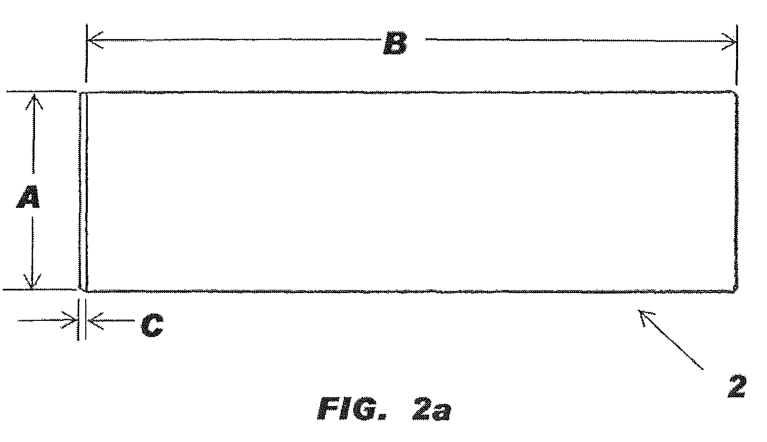
[0070]The retaining member in a second embodiment is preferably an angle bracket 19, as shown in FIG. 4c. The angle bracket 19 is preferably configured to have an L-shape with a first leg of the L preferably having a dimension A of between about 3½ and 4½ inches from the bend to the top edge of the angle bracket 19, and more preferably having a dimension of about 4 inches. The second leg of the L preferably has a dimension D of between about 2 and 3 inches from the bend to the front edge of the angle bracket, and more preferably having a dimension of about 2 inches. The angle bracket 19 preferably has a second dimension B of between about 4 and 10 feet, more preferably the angle bracket 19 has a second dimension that is between 7½ and 9½ feet, where most preferably the angle bracket has a second dimension that is 6 inches less than the width of the flexible material to which it is being attached. The angle bracket 19 preferably has a third dimension C of between about 3 / 32 and ⅜ of ...
third embodiment
[0071]The retaining member in a third embodiment is preferably a brick ledge box mounting bracket 43, as shown in FIG. 4d. The a brick ledge box mounting bracket 43 is preferably configured to have a flat central portion 432, a first edge portion angled back towards the central portion to thereby form a top flange 434 having acute angle between the flange and the central portion, and a box tube portion 436 extending from the central portion 432, wherein the central portion adjoins the box portion along a face of the box portion at a corner such that the central portion and box wall are flush and the box extends away from the central portion on the same side as the top flange. The top flange 434 is configured and dimensioned and the degree of the acute angle is selected to retain the second holding member, when the structural fastening apparatus is correctly installed. The top flange 434 preferably has a dimension of between ½ and 1¼ inches between the bend with the central portion a...
PUM
 Abstract
Description
Claims
Application Information