Noise control

Inactive Publication Date: 2010-01-19
ROLLS ROYCE PLC
View PDF14 Cites 17 Cited by
  • Summary
  • Abstract
  • Description
  • Claims
  • Application Information

AI Technical Summary

Benefits of technology

[0008]In accordance with the present invention there is provided a method of noise control for a plurality of blades mounted on a disc or hub to rotate within a housing whereby when rotating those blades cause noise, the method comprising;a) Determination of a noise attenuation frequency spectrum within the housing and any attenuation means associated with that housing;b) Determination of a noise frequency spectrum at the rotor face for the plurality of blades when specifically rotated; and,c) Rearranging specific blade positions upon the disc or hub to optimise the noise frequency spectrum for more consistency with the attenuation of the duct and any noise attenuation means for greater noise control.
[0011]Additionally, for B uneven blades and when the acoustic liner in the duct is most effective in the engine order range N to m then it is necessary to arrange the blades around the disc or hub to ensure the 1 to (N−1) Fourier coefficients (i.e. a lower frequency point of the most effective frequency for the acoustic liner to attenuate) and m to (B−1) Fourier coefficients of either one or more combinations of stagger, thickness, camber, lean, and leading edge blade angle of the blade set are reduced.
[0013]In addition to the arrangement of blades to control noise, the plurality of the blades may be arranged to also provide unbalance, blade stress or flutter limitation and / or to reduce stagger differences between adjacent blades and / or to control the variation in spacing of rotational shocks affecting higher frequency noise and / or to minimise blade to blade geometric differences.
[0015]Also, in accordance with the present invention there is a noise control arrangement for a plurality of blades mounted on a disc or hub to rotate within a duct whereby when rotating those blades cause noise, the duct including noise attenuation means with varying attenuation frequency response dependent upon noise frequency, and the blades mounted in specific order upon the disc or hub to enhance, upon rotation, the proportion of noise at the harmonic frequencies of higher attenuation by the noise attenuation means.
[0016]Advantageously, the plurality of the blades are also arranged to provide rotor unbalance, blade stress or flutter limitation and / or to reduce blade stagger angle differences between adjacent blades and / or to control spacing of rotational shocks and / or to minimise blade to blade geometric differences.
[0021]Additionally the blades may also be arranged at the same time to provide a minimal moment weight unbalance and / or minimal unevenness of tip rub against the fan case and / or minimal blade flutter characteristics. Limits for these parameters can also be incorporated into the method.

Problems solved by technology

Nevertheless, rotating machinery by its nature will create noise and in particular so called buzz saw noise generated by the rotating fan assembly.
The buzz-saw noise arises from the production of non-uniform shock waves resulting from the blade-to-blade geometric differences associated with the manufacturing tolerances of the rotor blades.
However such a reduction in tolerances will significantly increase the manufacturing cost of the rotor blades. FIG. 1 below shows an example, considering blade stagger angle alone, of the effect of a) all blades being identical b) the effect of one blade stagger angle being larger than the others.
From the above it will be appreciated that the principal problem relates to the non-uniformity of the rotating assembly geometry creating disparities in the regularity of shocks at the rotational speeds defined.
These disparities with respect to the adjacent casing or duct wall cause the associated buzz-saw noise.
Acoustic duct liner design for frequency and attenuation is usually compromised for different specific noise sources such as broadband noise or specific aircraft conditions such as approach, take-off or cruise.
Therefore the attenuation-frequency spectrum characteristic of the duct liner are usually far from ideal for the buzz-saw noise source considered here.
Nevertheless, there are commercial as well as practical limits to such approaches, i.e. more accurately manufactured and assembled blades will greatly increase costs.

Method used


Image

  • Noise control
  • Noise control
  • Noise control

Examples


Embodiment Construction

[0031]FIG. 3 is a schematic of a typical gas turbine engine. The engine comprises a fan assembly that has a plurality of blades 2 mounted on a disc or hub 4. The fan rotates within a housing 6 and helps to push air rewards thereby generating thrust.

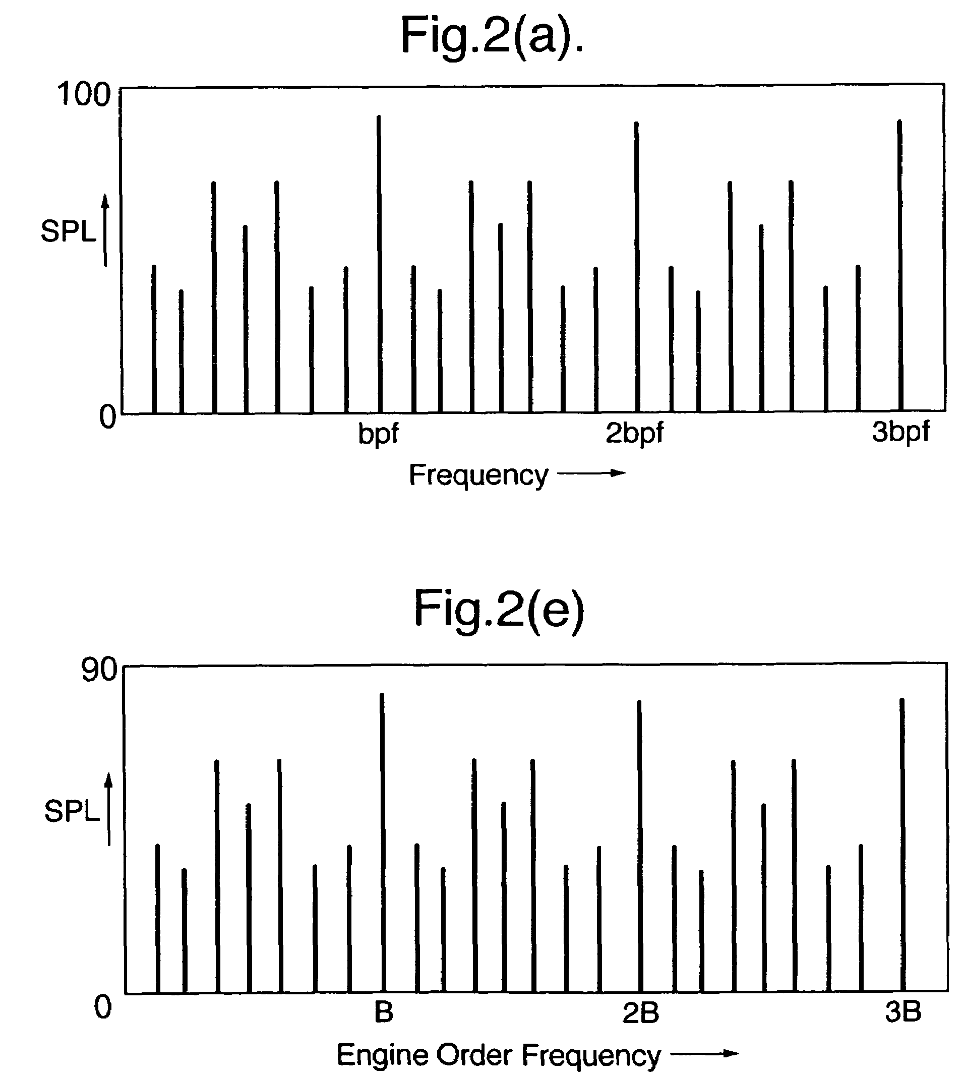
[0032]Referring to FIG. 2a, if a fan assembly consists of B unequal stagger angles, the buzz-saw noise spectrum is predicted using the stagger angles of the blades in order around the disc according to equation 2 above for each engine order (r) of blades. FIG. 2a shows a typical predicted buzz-saw noise spectrum obtained in this way. We note that the spectral character is symmetric about engine orders 0.5B, 1.5, 2.5B and 3.5B (in fact this is true also for 4.5B, 5.5B, . . . etc.). At each engine order B or multiple of B, the noise is that of the rotor-alone blade passing noise which would be produced even if there were no blade to blade differences. At other engine orders the noise is produced by the blade to blade differences (in this ca...


PUM


Abstract

Noise control with respect to rotating machinery such as gas turbine engines is important to meet acceptable operational and environmental constraints. Buzz-saw noise in particular is due to differences in blade to blade geometries both as assembled and due to blade manufacturing tolerance variations. Generally, a plurality of blades rotate within a duct and some noise propagates forwards of the blade assembly. In order to abate such noise an acoustic lining is provided. By consideration of the acoustic attenuation effects of that lining, it is possible to rearrange the blades within the blade assembly such that the overall noise attenuation effects are improved. Thus, the blade assembly may be rearranged such that there is a reduction in the Fourier coefficients at harmonics above and below the harmonics most attenuated by the acoustic attenuation treatment or lining or alternatively the effect of that lining maximized by rearrangement of the blades to shift the harmonics to those most attenuated by the acoustic treatment.

Description

FIELD OF THE INVENTION[0001]The present invention relates to noise control and more particularly to noise control with regard to rotating machinery such as a gas turbine engine.BACKGROUND OF THE INVENTION[0002]Control of noise is important as sensitivity to the perceived environment increases. Thus, such rotating machinery as gas turbine engines and in particular such engines used for aircraft operations are constantly reviewed in terms of noise targets. Clearly, these noise targets are increasingly stringent with an ongoing objective to reduce environmental and where appropriate aircraft cabin noise. Nevertheless, rotating machinery by its nature will create noise and in particular so called buzz saw noise generated by the rotating fan assembly.[0003]Buzz-saw noise occurs when the fan assembly operates with the rotor blade tips—or a lower span of the rotor blades—at sonic or supersonic Mach numbers, i.e. when Mr>1. Where Mr is the resultant rotor relative tip Mach number associa...

Claims


Application Information

Patent Timeline
IPC IPC(8): F04D29/66F01D5/14F02C7/045
CPCF02C7/045Y02T50/671F05D2260/96Y02T50/60
Inventor SCHWALLER, PETER J GSMITH, NIGEL H S
Owner ROLLS ROYCE PLC
Why Eureka
Try Eureka