Microneedle structure and production method therefor

a microneedle and production method technology, applied in the direction of liquid/fluent solid measurement, other medical devices, intravenous devices, etc., can solve the problems of reducing the effectiveness of the structure, and affecting the effect of the structur

Inactive Publication Date: 2010-01-19
NANOPASS TECH LTD
View PDF27 Cites 107 Cited by
  • Summary
  • Abstract
  • Description
  • Claims
  • Application Information

AI Technical Summary

Problems solved by technology

While hollow microneedles are potentially an effective structure for delivering fluids across the dermal barrier, the structures proposed to-date suffer from a number of drawbacks.
This punching action tends to cause damage to the skin.
Additionally, the punched material tends to form a plug which at least partially obstructs the flow path through the microneedle.
This is particularly problematic where withdrawal of fluids is required since the suction further exacerbates the plugging of the hollow tube within the microneedle.
The flat ended form of the needles also presents a relatively large resistance to penetration of the skin, reducing the effectiveness of the structure.
This, however, is at the cost of very limited density of microneedles (either a single microneedle, or at most, a single row of needles), leading to corresponding severe fluid flow rate limitations.
The very long proposed needle (about 3 mm) of Smart et al. suffers from an additional very high risk of needle breakage.
While the techniques described in the aforementioned co-pending application produce highly effective microneedle structures, various disadvantages are encountered while implementing such techniques in commercial production.
Firstly, conventional deep reactive ion etching (DRIE) is generally sufficiently inaccurate to reduce the usable yield to unacceptably low proportions.
This option, however, greatly reduces the rate at which material can be etched away.
As a result, these techniques are inefficient processing large areas of a wafer.
Wet techniques are not, however, suited for directly achieving the asymmetrical forms required for implementation of the microneedles.
A further shortcoming of microneedle structures made by micromachining techniques is the brittleness of the resulting microneedles.
Microneedles made from silicon or silicon dioxide are highly brittle.
As a result, a significant proportion of the microneedles may fracture due to the stresses occurring during penetration, leaving fragments of the material within the tissue.
Furthermore, oblique insertion by an unskilled person could lead to fracture of a very large proportion of the needles, resulting in malfunction of the device.

Method used


Image

  • Microneedle structure and production method therefor
  • Microneedle structure and production method therefor
  • Microneedle structure and production method therefor

Examples


Embodiment Construction

[0036]The present invention is a method for producing hollow microneedles using a sequence of dry and wet etching techniques, and a hollow microneedle structure produced by such techniques.

[0037]The principles and operation of production techniques and the resulting structures according to the present invention may be better understood with reference to the drawings and the accompanying description.

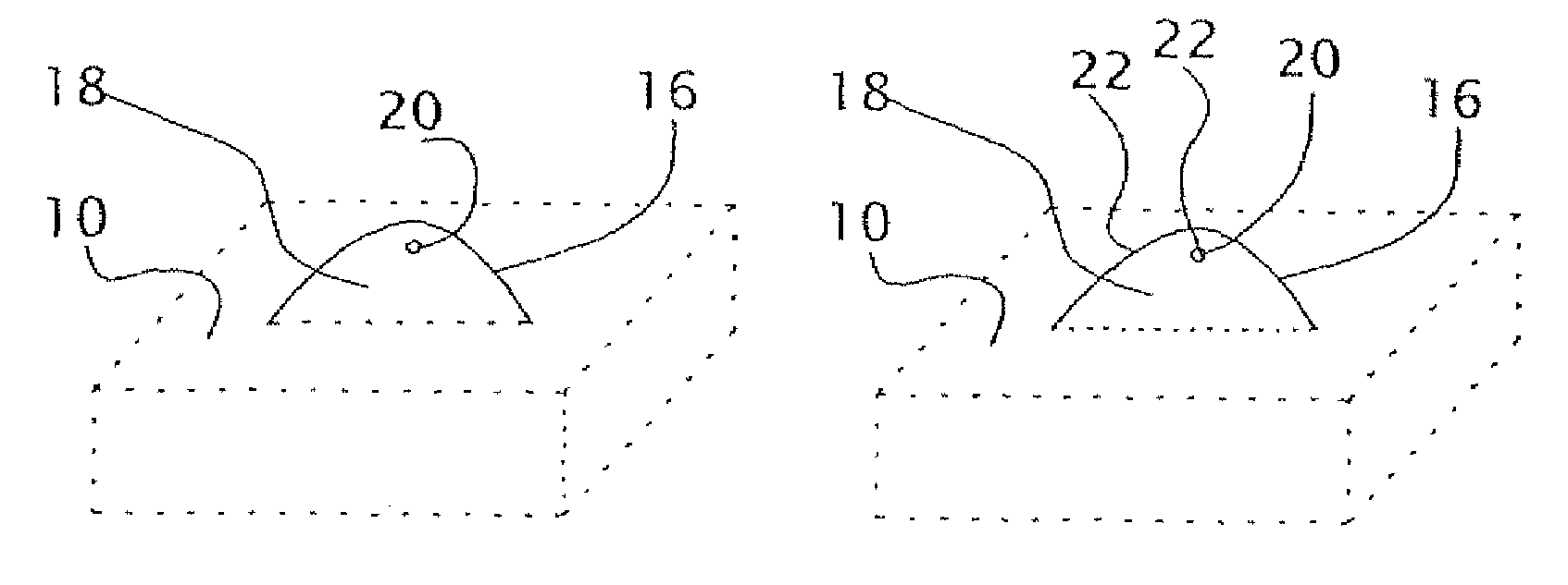
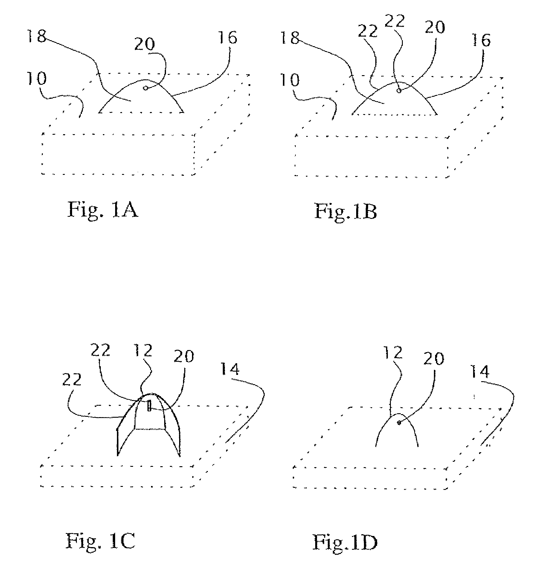
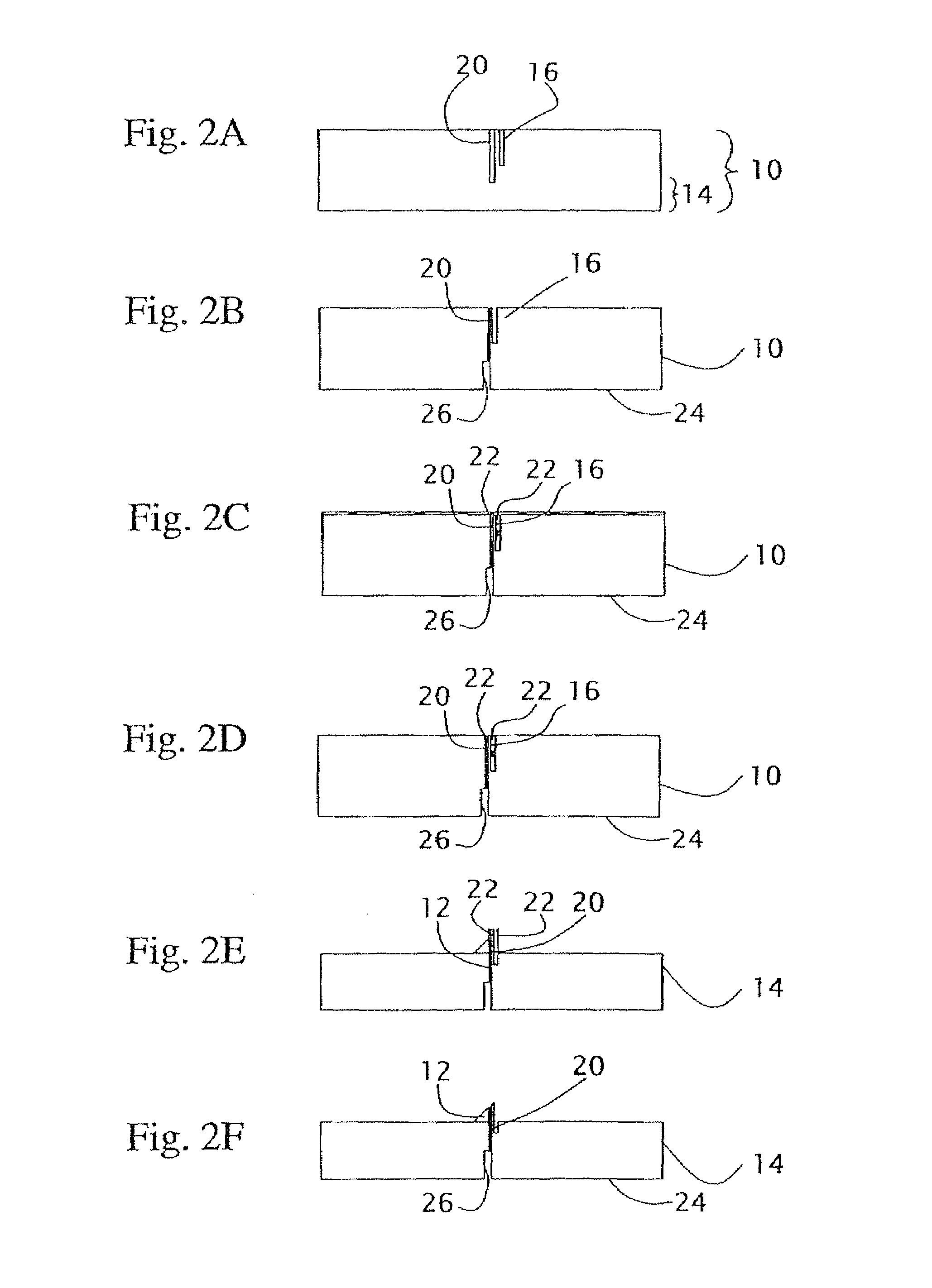
[0038]Turning now to the drawings, FIGS. 1A-1D and 2A-2F illustrate schematically a method for processing a wafer 10 to form a plurality of hollow microneedles 12 projecting from a substrate 14.

[0039]Generally speaking, the method first employs a dry etching process to form a plurality of groups of recessed features, each group of recessed features including at least one slot 16 deployed to form an open shape having an included area 18 and at least one hole 20 located within included area 18. One such group of features is shown in FIGS. 1A and 2A.

[0040]Internal surfaces of holes 20 and sl...


PUM

PropertyMeasurementUnit
angleaaaaaaaaaa
angleaaaaaaaaaa
angleaaaaaaaaaa

Abstract

A method for processing a wafer to form a plurality of hollow microneedles projecting from a substrate includes forming, by use of a dry etching process, a number of groups of recessed features, each including at least one slot deployed to form an open shape having an included area and at least one hole located within the included area. The internal surfaces of the holes and the slots are then coated with a protective layer. An anisotropic wet etching process is then performed in such a manner as to remove material from outside the included areas while leaving a projecting feature within each of the included areas. The protective layer is then removed to reveal the microneedles.

Description

FIELD AND BACKGROUND OF THE INVENTION[0001]The present invention relates to microneedle structures and, in particular, it concerns a microneedle production method and the microneedle structure produced thereby.[0002]Much research has been directed towards the development of microneedles formed on chips or wafers by use of micro-machining techniques. This approach promises the possibility of producing numerous, very small needles which are sufficient to form small perforations in the dermal barrier, thereby overcoming the molecular size limitations of conventional transdermal patches, while being safe for use by unqualified personnel. Examples of such work may be found in PCT Publication No. WO 99 / 64580 to Georgia Tech Research Corp., as well as in the following scientific publications: “Micro machined needles for the transdermal delivery of drugs”, S. H. S. Henry et al. (MEMS 98, Heildelberg, Germany, January 1998); “Three dimensional hollow micro needle and microtube arrays”, D. V....

Claims


Application Information

Patent Timeline
Patent Type & Authority Patents(United States)
IPC IPC(8): A61M5/00B81C1/00A61M5/32A61M37/00B81B1/00
CPCA61M37/0015B81C1/005A61M2037/003A61M2037/0053B81B2203/0361
Inventor YESHURUN, YEHOSHUAHEFETZ, MIERDE BOER, MEINTBERENSCHOT, J. W.GARDENIERS, J. G. E.
Owner NANOPASS TECH LTD
Why Eureka
Try Eureka