[0016]Accordingly, it is a principle object and advantage of the present invention to overcome some or all of these limitations and to provide an improved design for a substrate support system. Another object and advantage of the present invention is to provide a simple, versatile substrate holder that facilitates reduced backside deposition and autodoping. Another object and advantage of the present invention is to provide a system and method in which a forced flow of gas inhibits both backside deposition and autodoping. Another object and advantage of the present invention is to provide a hollow support member for supporting the underside of the substrate holder and conveying the forced flow of gas upward into passages of the substrate holder. Another object and advantage of the present invention is to configure this hollow support member so that the upwardly conveyed gas migrates somewhat slowly and indirectly to the substrate backside to thereby reduce the risk of localized cooling in the substrate. Other objects and advantages of the present invention will be understood from the description below.
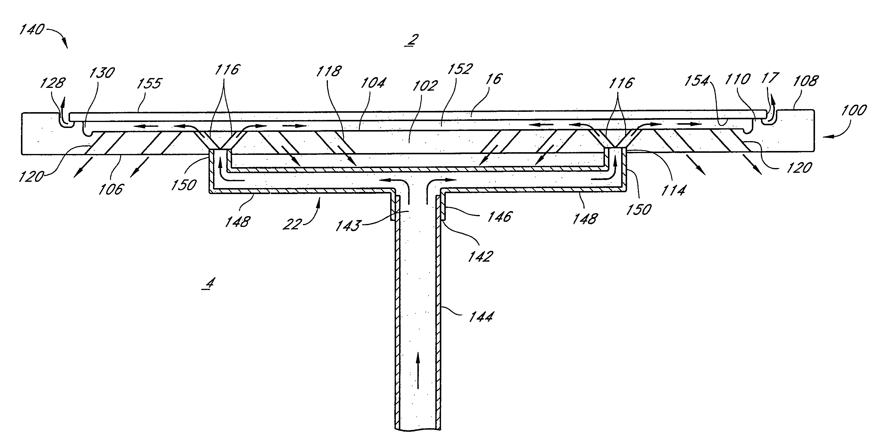
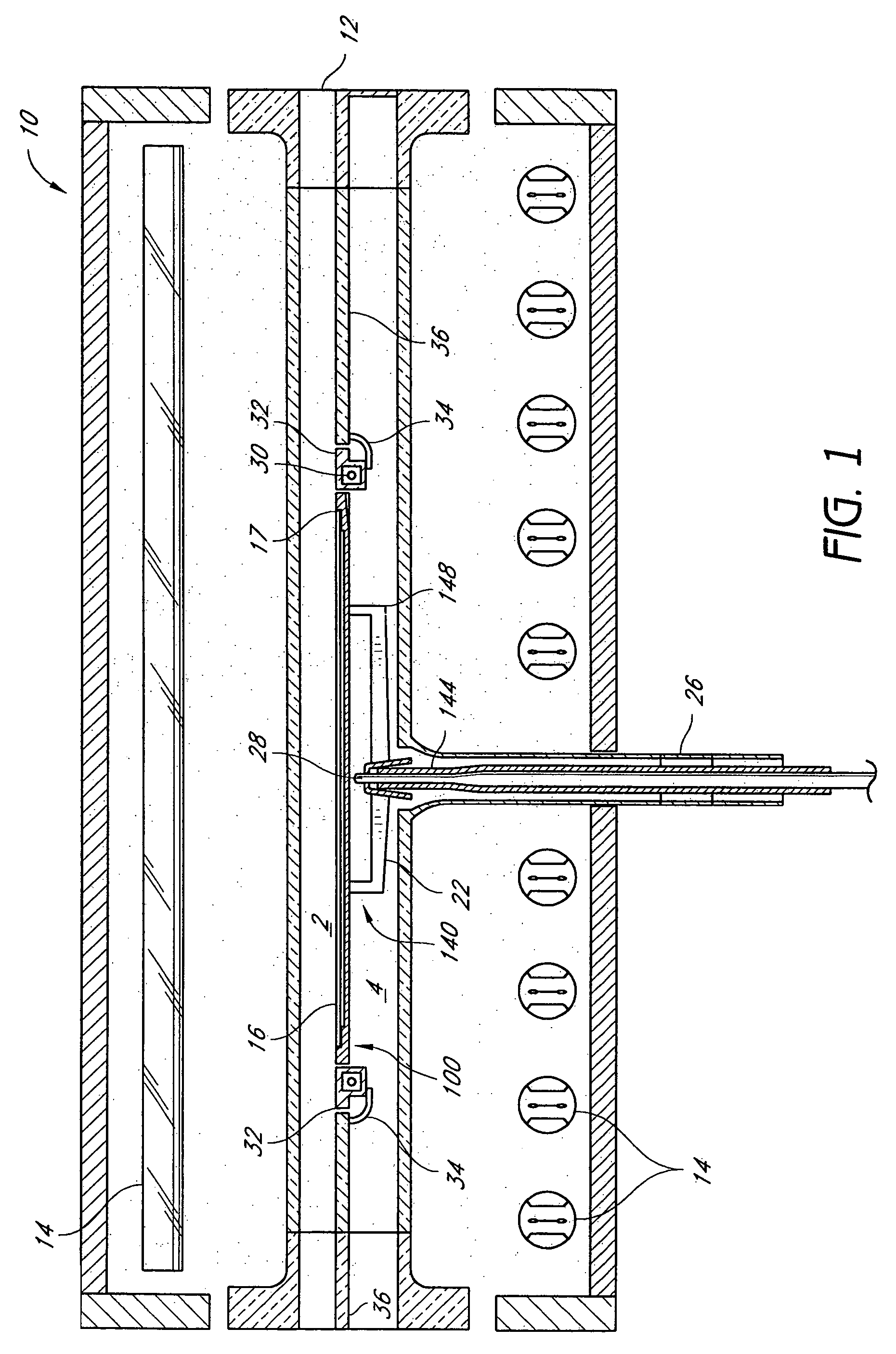
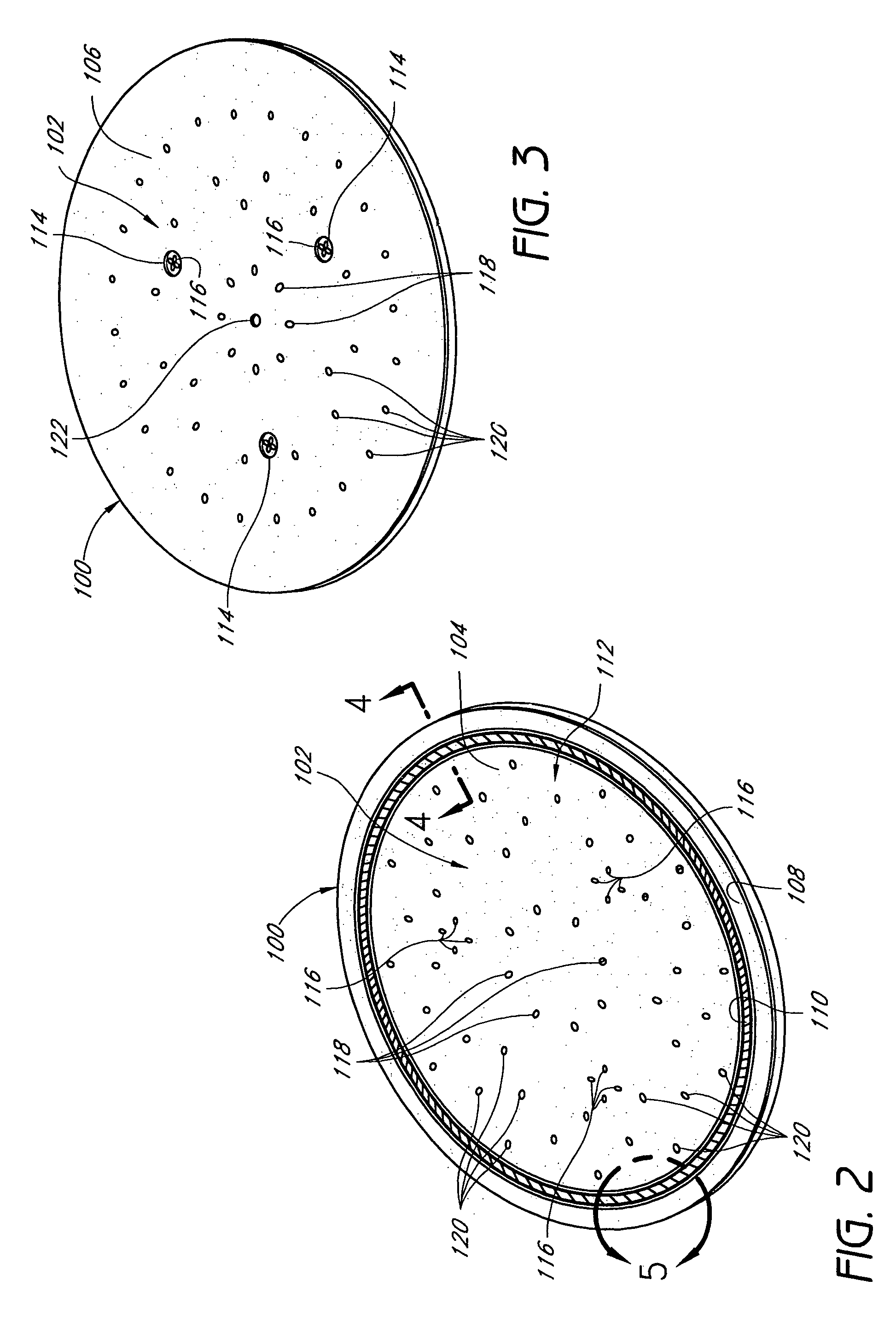
[0017]In one aspect, the present invention provides a substrate support system comprising a substrate holder for holding a substrate. The substrate holder comprises a central portion, at least one spacer extending upward from the central portion, and a hollow support member. The central portion has an upper surface, a lower surface, and a plurality of open passages extending from the upper surface to the lower surface. The at least one spacer has an upper support surface raised above the upper surface of the central portion. The at least one spacer's upper support surface is configured to support a peripheral portion of the substrate so that a gap region exists between the upper surface of the central portion and a bottom surface of the substrate. The hollow support member has an inlet adapted to engage an outlet of a gas-conveyor to facilitate gas flow from the gas-conveyor into the hollow support member. The hollow support member also has one or more upper open ends adapted to support the lower surface of the central portion of the substrate holder. The one or more upper open ends are configured to convey gas upward into lower ends of one or more of the passages in the central portion of the substrate holder. At least one of the passages has a lower end open to a region that is not inside the hollow support member.
[0018]In another aspect, the present invention provides a substrate support system comprising a substrate holder for holding a substrate, and a hollow support spider. The substrate holder comprises a central portion and a plurality of spacers extending upward therefrom. The central portion has an upper surface, a lower surface, and a plurality of passages extending from the upper surface to the lower surface. The spacers have upper support surfaces raised above the upper surface of the central portion. The spacers' upper support surfaces are configured to support a peripheral portion of the substrate so that a gap region exists between the upper surface of the central portion and a bottom surface of the substrate. The support spider comprises a hollow manifold and a plurality of hollow arms extending generally radially outward and upward therefrom. The manifold has an inlet adapted to engage an outlet of a gas-conveyor to facilitate gas flow from the gas-conveyor into the manifold. The hollow arms are configured to receive gas flow from the manifold. The hollow arms have open upper ends adapted to support the lower surface of the central portion of the substrate holder. The open upper ends of the hollow arms are configured to convey gas upward into a subset of the passages of the central portion of the substrate holder.
[0019]In another aspect, the present invention provides a substrate support system comprising a substrate holder for holding a substrate, and a hollow support member. The substrate holder comprises a generally planar central portion and a plurality of spacers extending upward therefrom. The central portion has an upper surface, a lower surface, and a plurality of open passages extending from the upper surface to the lower surface. The spacers have upper support surfaces raised above the upper surface of the central portion. The spacers' upper support surfaces are configured to support a peripheral portion of the substrate so that a gap region exists between the upper surface of the central portion and a bottom surface of the substrate. The hollow support member comprises a lower base member and an annular wall extending upward therefrom. The base member has an inlet adapted to engage an outlet of a gas-conveyor to facilitate gas flow from the gas-conveyor into the hollow support member. The annular wall has an upper edge configured to support a bottom surface of the substrate holder so that gas within the annular wall and between the base member and the bottom surface of the substrate holder is substantially prevented from flowing between the upper edge of the annular wall and the bottom surface of the substrate holder. The upper edge of the annular wall defines an upper opening of the hollow support member. This upper opening is configured to convey gas upward into lower ends of at least 10 of the passages of the central portion of the substrate holder.
[0020]In another aspect, the present invention provides a substrate holder for holding a substrate, comprising a central portion and a plurality of spacers extending upward therefrom. The central portion has an upper surface, a lower surface, a first set of open passages extending from the upper surface to the lower surface, and a second set of open passages each extending from the upper surface to one of a plurality of recesses within the lower surface. Each of the recesses is adapted to receive one of a plurality of corresponding upper ends of tubular arms of a hollow support member configured to support the central portion and convey gas upward into the second set of passages. The spacers have upper support surfaces raised above the upper surface of the central portion. The spacers' upper support surfaces are configured to support a peripheral portion of the substrate so that a gap region exists between the upper surface of the central portion and a bottom surface of the substrate.
[0021]In yet another aspect, the present invention provides a hollow support member for supporting a substrate holder that is in turn configured to support a substrate during substrate processing. The hollow support member comprises a base member and an annular wall extending upward therefrom. The base member has a lower inlet adapted to engage an upper end of a hollow tube to facilitate upward gas flow from the tube into the hollow support member. The annular wall has an upper edge configured to support a bottom surface of the substrate holder so that gas within the annular wall and between the base member and the bottom surface of the substrate holder is substantially prevented from flowing between the upper edge of the annular wall and the bottom surface of the substrate holder. The upper edge defines an upper opening of the hollow support member. The upper opening defines an area of at least 70% of the size of a substrate that the substrate holder is specifically designed to support.


