
System and method for three-dimensional video coding

a three-dimensional video and video coding technology, applied in the field of video compression, can solve the problems of poor coding efficiency, higher complexity, and the poor coding efficiency of composite frame methods, and achieve the effect of improving compression

Inactive Publication Date: 2010-01-19
SHARP KK
View PDF23 Cites 92 Cited by
  • Summary
  • Abstract
  • Description
  • Claims
  • Application Information

AI Technical Summary

Benefits of technology

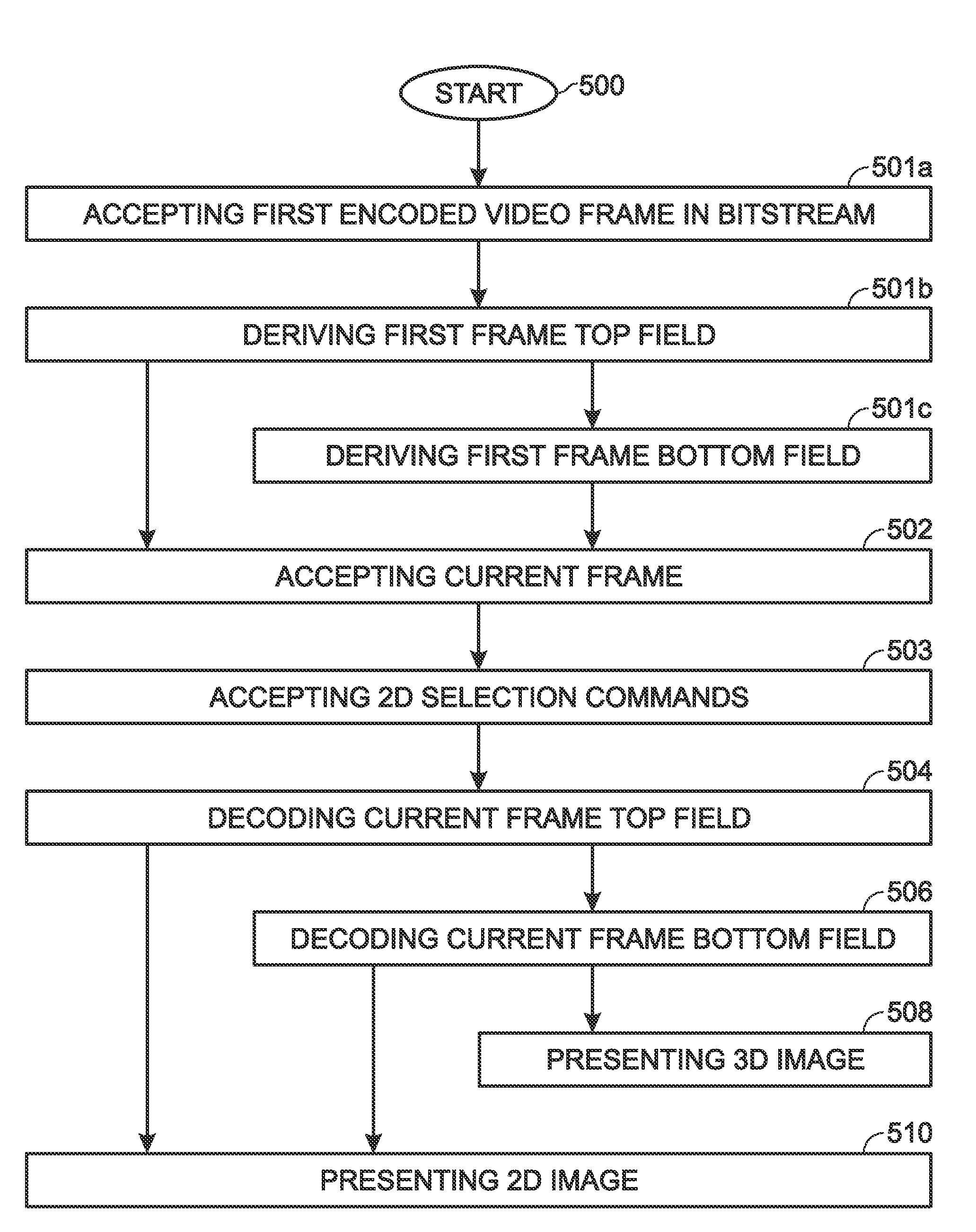
The present invention is about treating 3D video frames as interlaced materials to improve compression. It supports a scalable coding feature with minimal restrictions on the encoder side. The invention also allows for decoding of the top and bottom fields separately to create a stereo-view image. The method includes accepting a bitstream with a current video frame encoded with two interlaced fields, decoding the top and bottom fields separately, and presenting them as a 3D frame image. The invention also provides a method for encoding 3D video, which involves encoding the first view as a frame top field and the second view as a frame bottom field, and transmitting a bitstream with the current video frame. The technical effects of the invention include better compression and improved viewing experience for 3D video.

Problems solved by technology

This straightforward method, however, suffers from poor coding efficiency.
It also has higher complexity because it needs to encode / decoder, multiplex / demultiplex, and synchronize two bitstreams.
This composite-frame method still suffers from poor coding efficiency.
However, this method still has higher complexity due to its needs to handle multiple bitstreams (base-layer and enhanced-layer bitstreams).

Method used


Image

  • System and method for three-dimensional video coding
  • System and method for three-dimensional video coding
  • System and method for three-dimensional video coding

Examples


Embodiment Construction

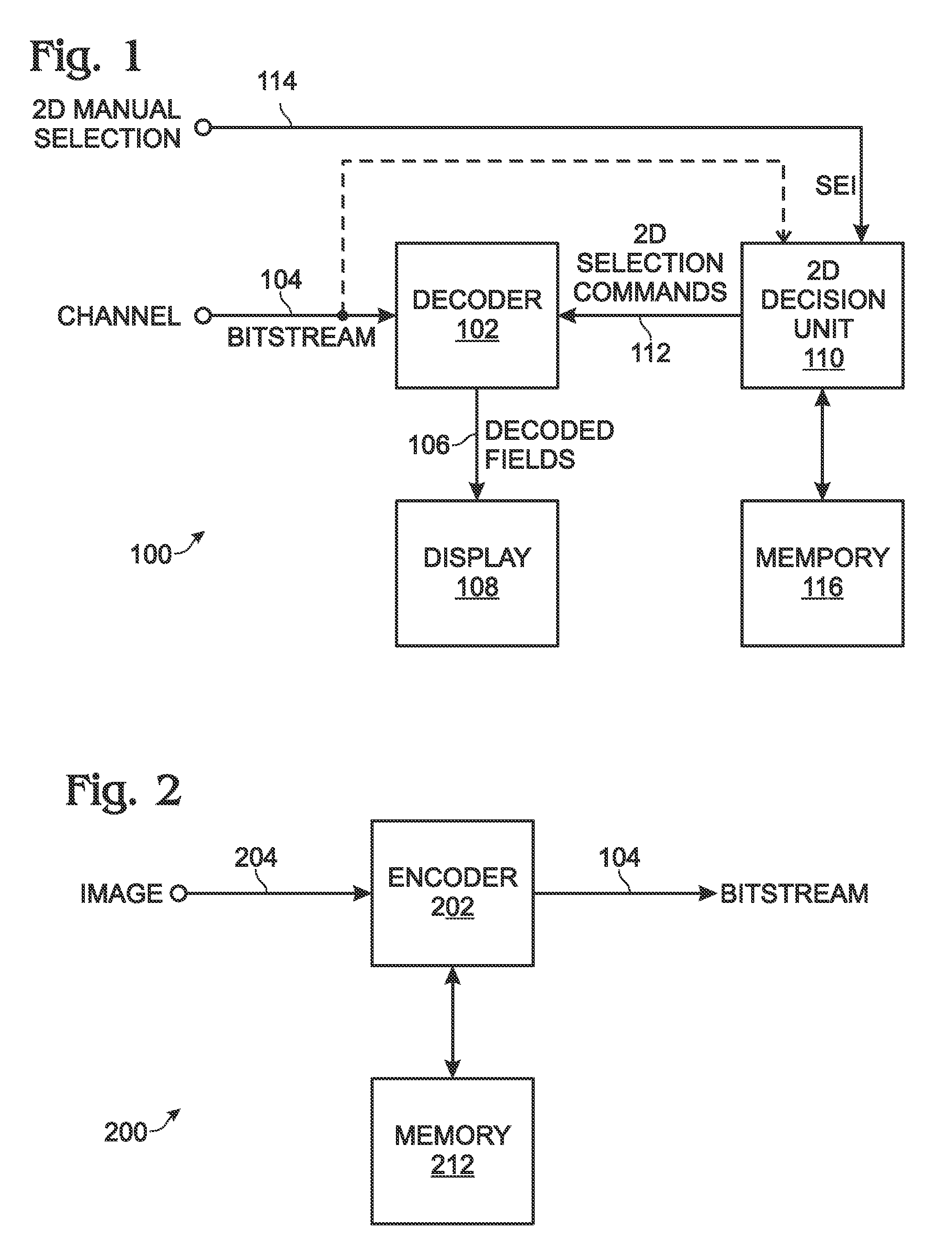
[0022]FIG. 1 is a schematic block diagram of the present invention 3D video receiver system. The system 100 comprises a decoder 102 having an input connected to a channel on line 104 to accept a bitstream with a current video frame encoded with two interlaced fields. For example, line 104 may be connected to the Internet, a satellite receiver, or a digital cable network. The decoder 102 accepts the bitstream in a standard such as MPEG2, MPEG4, or ITU-T H.264. The decoder 102 has an output on line 106 to supply a decoded current frame top field and current frame bottom field. A display 108 has an input to accept the decoded fields on line 106. The display 108 visually presents the decoded top and bottom fields as a 3D frame image. For example, the display 108 can be a high-definition TV. In other aspects of the system, the display 108 visually presents the decoded top and bottom fields as a stereo-view image.

[0023]Generally, the display 108 may visually presents a two-dimensional (2D...


PUM


Abstract

Systems and methods are provided for receiving and encoding 3D video. The receiving method comprises: accepting a bitstream with a current video frame encoded with two interlaced fields, in a MPEG2, MPEG4, or H.264 standard; decoding a current frame top field; decoding a current frame bottom field; and, presenting the decoded top and bottom fields as a 3D frame image. In some aspects, the method presents the decoded top and bottom fields as a stereo-view image. In other aspects, the method accepts 2D selection commands in response to a trigger such as receiving a supplemental enhancement information (SEI) message, an analysis of display capabilities, manual selection, or receiver system configuration. Then, only one of the current frame interlaced fields is decoded, and a 2D frame image is presented.

Description

RELATED APPLICATIONS[0001]This application claims the benefit of a provisional application entitled, SYSTEMS AND METHODS FOR STEREO VIDEO CODING, invented by Lei et al., Ser. No. 60,512,155, filed Oct. 16, 2003.[0002]This application claims the benefit of a provisional application entitled, SYSTEMS AND METHODS FOR STEREO VIDEO CODING, invented by Lei et al., Ser. No. 60,519,482, filed Nov. 13, 2003.BACKGROUND OF THE INVENTION[0003]1. Field of the Invention[0004]This invention generally relates to video compression and, more particularly, to a system and method of encoding / decoding compressed video for three-dimensional and stereo viewing.[0005]2. Description of the Related Art[0006]Conventional video compression techniques typically handle three-dimensional (3D), or stereo-view video, in units of a frame. The most straightforward method is to code two views separately, as independent video sequences. This straightforward method, however, suffers from poor coding efficiency. It also ...

Claims


Application Information

Patent Timeline
Patent Type & Authority Patents(United States)
IPC IPC(8): G06K9/36H04N7/26H04N7/32H04N7/50H04N13/00H04N13/04
CPCH04N19/597H04N19/70H04N19/172H04N19/44H04N19/12H04N19/162H04N19/164H04N19/61
Inventor LEI, SHAWMINSUN, SHIJUN
Owner SHARP KK
Learn More