

Method for removing vapor within heat pipe
a technology of vapor removal and heat pipe, which is applied in the direction of motor/generator/converter stopper, dynamo-electric converter control, lighting and heating apparatus, etc., can solve the problem of poor control quality of heat pipes, inability to precisely control the remaining amount of working fluid within heat pipes, poor heat flow effect, etc. problem, to achieve the effect of improving quality, stable amount of working fluid, and improving heat flow
- Summary
- Abstract
- Description
- Claims
- Application Information
AI Technical Summary
Benefits of technology
Problems solved by technology
Method used
Image

Examples
Embodiment Construction
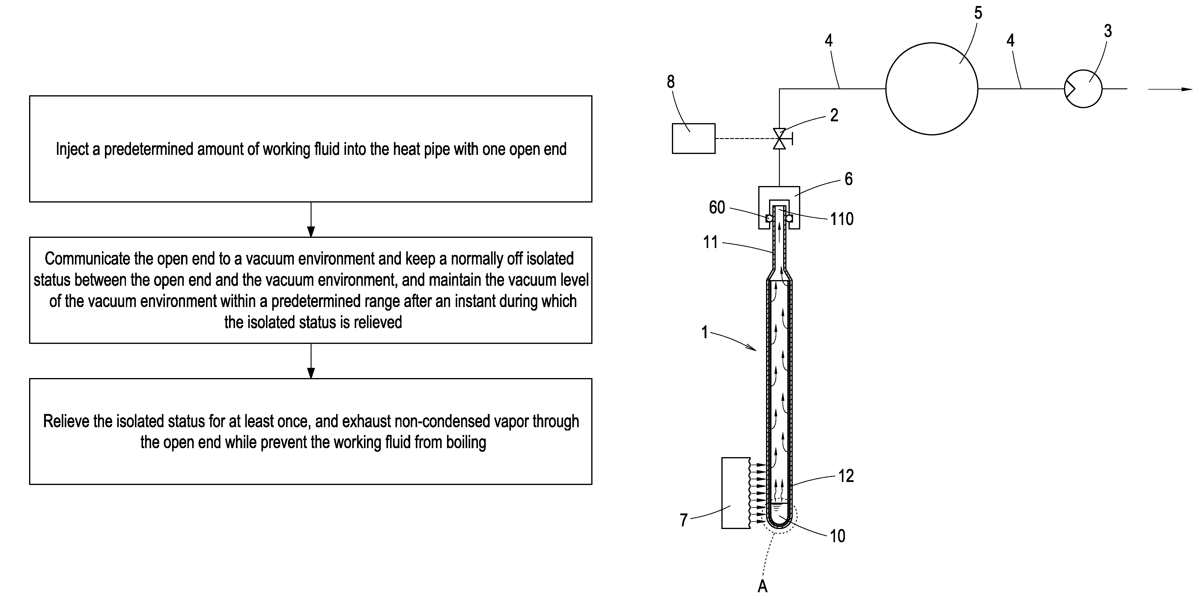
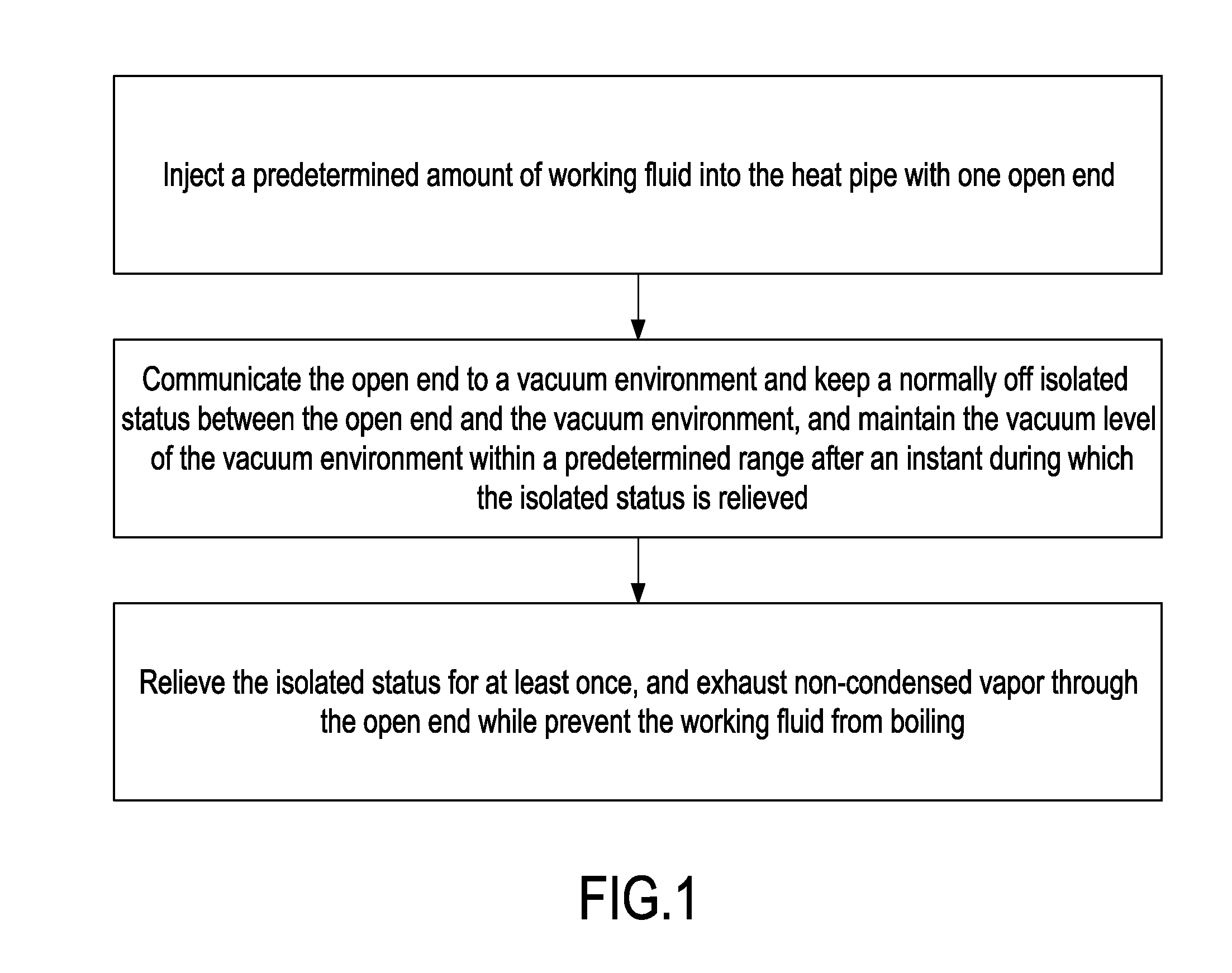
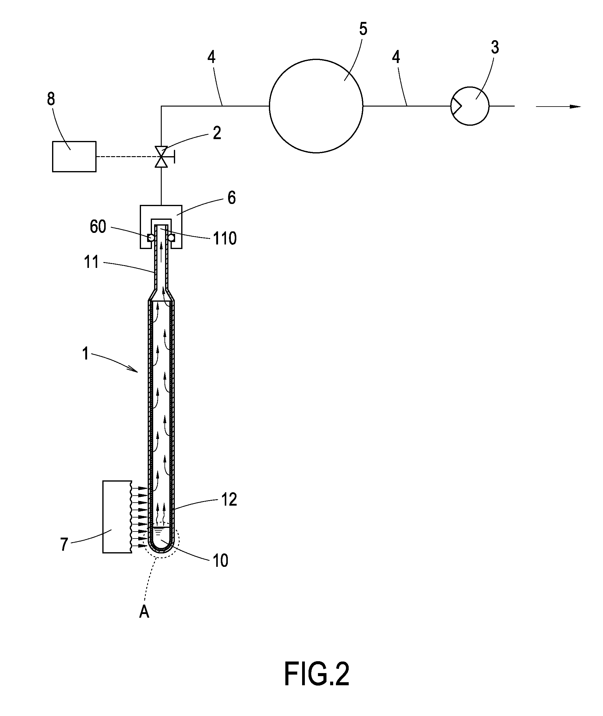
[0014]Referring to FIGS. 1 and 2, the process flow of the method and operation of the apparatus for removing vapor within a heat pipe provided by the present invention are illustrated. The method includes injecting a predetermined amount of working fluid 10 into a heat pipe 1 (as shown in FIG. 3). An opening 110 is reserved at one end of the heat pipe 1. Preferably, the predetermined amount is slightly more than the amount of working fluid to be sealed in the heat pipe 1. The interior wall of the heat pipe 1 includes wick structure 12, while the opening is formed at the sealing end 11 of the heat pipe.
[0015]The opening 110 is communicated to a vacuum environment. The communication between the opening 110 and the vacuum environment is normally disconnected. At the communication between the opening 110 and the vacuum environment is connected, the vacuum level of the vacuum environment is maintained within a certain range. This is achieved by continuously pumping the vacuum environment...
PUM
| Property | Measurement | Unit |
|---|---|---|
| vacuum level | aaaaa | aaaaa |
| boiling | aaaaa | aaaaa |
| temperature | aaaaa | aaaaa |
Abstract
Description
Claims
Application Information