
Variable speed drive device for bicycle

a variable speed drive and bicycle technology, applied in the direction of mechanical control devices, gearing, instruments, etc., can solve the problems of complicated overall structure of the variable speed drive device, and achieve the effect of simple structure and reduced motor torqu

Inactive Publication Date: 2010-01-26
SHIMANO INC
View PDF17 Cites 16 Cited by
  • Summary
  • Abstract
  • Description
  • Claims
  • Application Information

AI Technical Summary

Benefits of technology

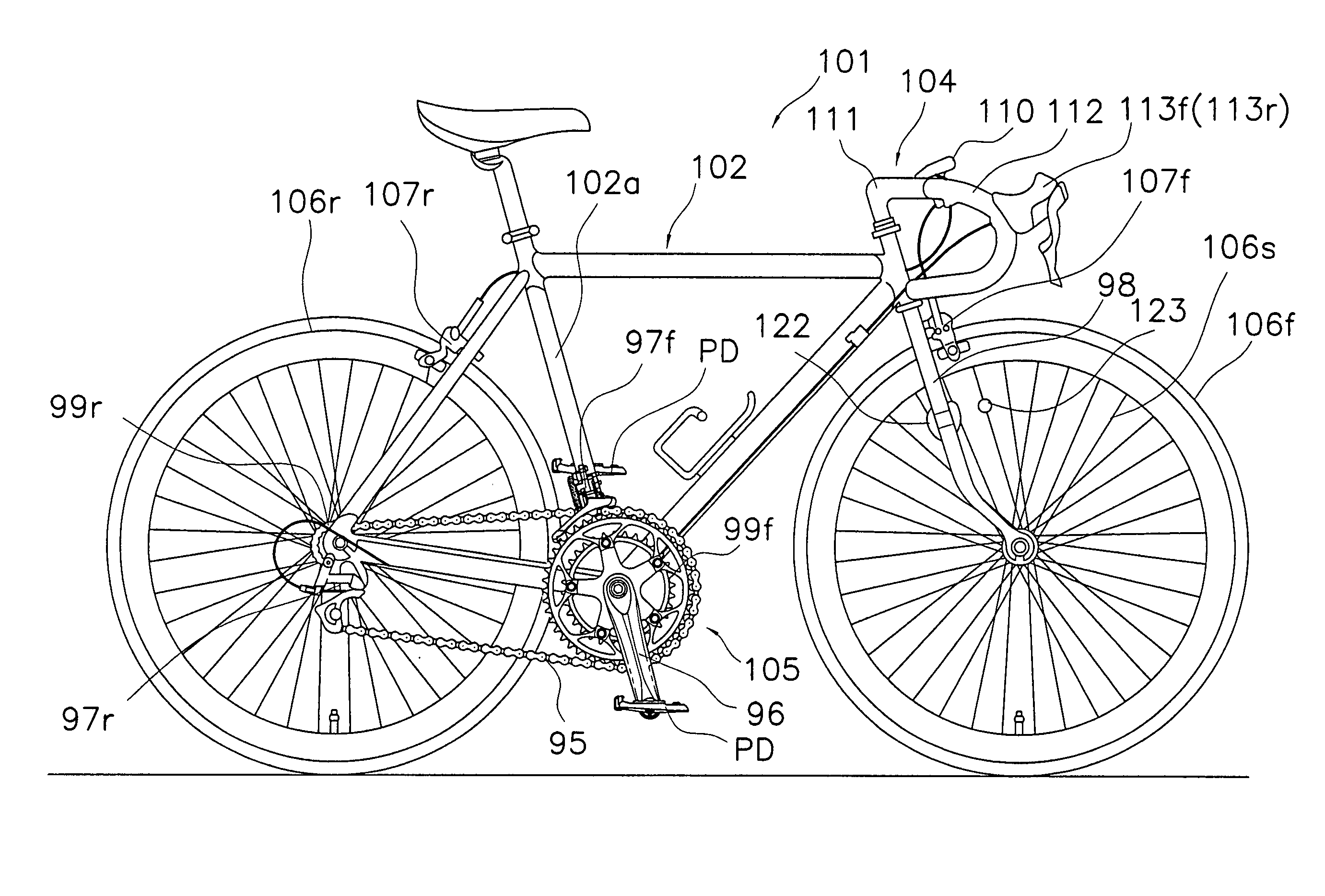
The present invention provides a variable speed drive device for bicycles that reduces the level of motor torque required for gear shifting with a simple structure. The device includes a case member, a motor drive mechanism, and a linking structure. The linking structure has a retaining portion that retains a transmission member, and the length of a hypothetical arm line measured extending from a center of rotation of the motor drive mechanism perpendicularly to a longitudinal axis of the transmission member changes depending on a rotational phase of the motor drive mechanism when the transmission member is attached to the retaining portion. This reduces the size of the motor required and simplifies the overall structure of the device.

Problems solved by technology

However, since mechanisms such as the cam mechanism and the biasing mechanism with the coil spring member are needed in the conventional variable speed drive device disclosed in the above mentioned reference, the overall structure of the variable speed drive device become complicated.

Method used


Image

  • Variable speed drive device for bicycle
  • Variable speed drive device for bicycle
  • Variable speed drive device for bicycle

Examples


second embodiment

[0057]Referring now to FIG. 13, a variable speed drive device 120 in accordance with a second embodiment will now be explained. In view of the similarity between the first and second embodiments, the parts of the second embodiment that are identical to the parts of the first embodiment will be given the same reference numerals as the parts of the first embodiment.

[0058]The second embodiment of the present invention is basically identical to the first embodiment except for the structure of a cable linking portion 163. More specifically, in the first embodiment described above, the length L of the hypothetical arm line AR is made variable by providing the first and second arm members 90 and 91 in the cable linking portion 62. However, in the second embodiment as shown in FIG. 13, the cable linking portion 163 comprises a cam member 191 having a retaining portion 192 for retaining the shift cable 21, and a cable guide groove 193 for guiding the shift cable 21 toward the retaining porti...


PUM


Abstract

A front variable speed drive device is configured and arranged to electrically operate driving of a front derailleur by a shift cable. The front variable speed drive device comprises a case member, a motor drive mechanism, and a cable linking portion. The case member is mounted on a hanger portion of a bicycle frame. The motor drive mechanism is mounted on the case member, and has a revolving shaft. The cable linking portion has a retaining portion configured and arranged to retain a first end of the shift cable. The cable linking portion is rotatably mounted on the revolving shaft, and has a hypothetical arm line extending in the direction perpendicular to the shift cable from the center of rotation with a length of the hypothetical arm line changing depending on the rotation phase. Thus, motor torque required for shifting gears is reduced with a simple structure.

Description

CROSS-REFERENCE TO RELATED APPLICATIONS[0001]This application claims priority to Japanese Patent Application No. 2004-177331. The entire disclosure of Japanese Patent Application No. 2004-177331 is hereby incorporated herein by reference.BACKGROUND OF THE INVENTION[0002]1. Field of the Invention[0003]The present invention relates to a variable speed drive device for a bicycle. More specifically, the present invention relates to a variable speed drive device for a bicycle adapted to be coupled to a variable speed gearshift device via a transmission member to electrically drive the variable speed gearshift device.[0004]2. Background Information[0005]Japanese Patent No. 3423285 discloses a conventional variable speed drive device used in a bicycle that is configured and arranged to electrically operate driving of a bicycle derailleur, an internal shift hub, or other variable speed gearshift via a shift cable or other transmission member. This conventional variable speed drive device ha...

Claims


Application Information

Patent Timeline
Patent Type & Authority Patents(United States)
IPC IPC(8): F16H9/00G05G1/04B62K23/06B62M9/122B62M9/132B62M11/06B62M25/08
CPCB62K23/06B62M9/132B62M9/1348B62M25/08Y10T74/20558Y10T74/20582Y10T74/18184
Inventor ICHIDA, TADASHIFUJII, KAZUHIRO
Owner SHIMANO INC
Learn More