Inductive position sensor

a position sensor and inductive technology, applied in the direction of instruments, measuring devices, coils, etc., can solve the problems of causing measuring distortion by the same magnetic field, and achieve the effects of smoothing out distortion, reducing gap, and weak coupling via the scal

Active Publication Date: 2010-01-26
MELIUS
View PDF7 Cites 26 Cited by
  • Summary
  • Abstract
  • Description
  • Claims
  • Application Information

AI Technical Summary

Benefits of technology

[0008]For the obviously desirable coupling via the scale between any drive and sense winding within one winding element pattern, the inverted coupling polarity and the scale shift of NT+T / 2 combine, so that for any displacement, the variation of the coupled signal within each winding element pattern is the same. As a result, the spatially periodic coupled signals from each winding element pattern reinforce each other. If the spatially periodic coupled signal within one winding element pattern is biased, i.e. has a non-zero average value over one spatial period T, it is cancelled by the other winding element signal's bias, because of the inverted coupling polarity. This is of advantage, as it is easier to determine the spatial phase and amplitude of an unbiased signal. Moreover, measuring distortions of spatial period T due to uneven coupling via the scale are reduced, as the contributions from each winding element pattern, mutually shifted by T / 2, tend to oppose each other.
[0009]Each winding's at least one pair of winding elements is optimally connected in series. This forces the same current through the drive winding elements of a same drive winding, thereby eliminating the effect of current mismatch between both winding element patterns. It also maximizes the voltage signal picked up by the sense windings.
[0010]A minimum separation is required between winding element patterns to avoid unwanted cross-coupling from one pattern's drive windings to the other pattern's sense windings. Advantageously, shielding in form of a conducting plane nearby attenuates the mutual inductances between winding elements. This allows a smaller separation between patterns, hence a shorter sensor.

Problems solved by technology

Unfortunately, uneven direct coupling between interlaced windings sharing the same magnetic field creates measuring distortions.

Method used


Image

  • Inductive position sensor
  • Inductive position sensor
  • Inductive position sensor

Examples


first embodiment

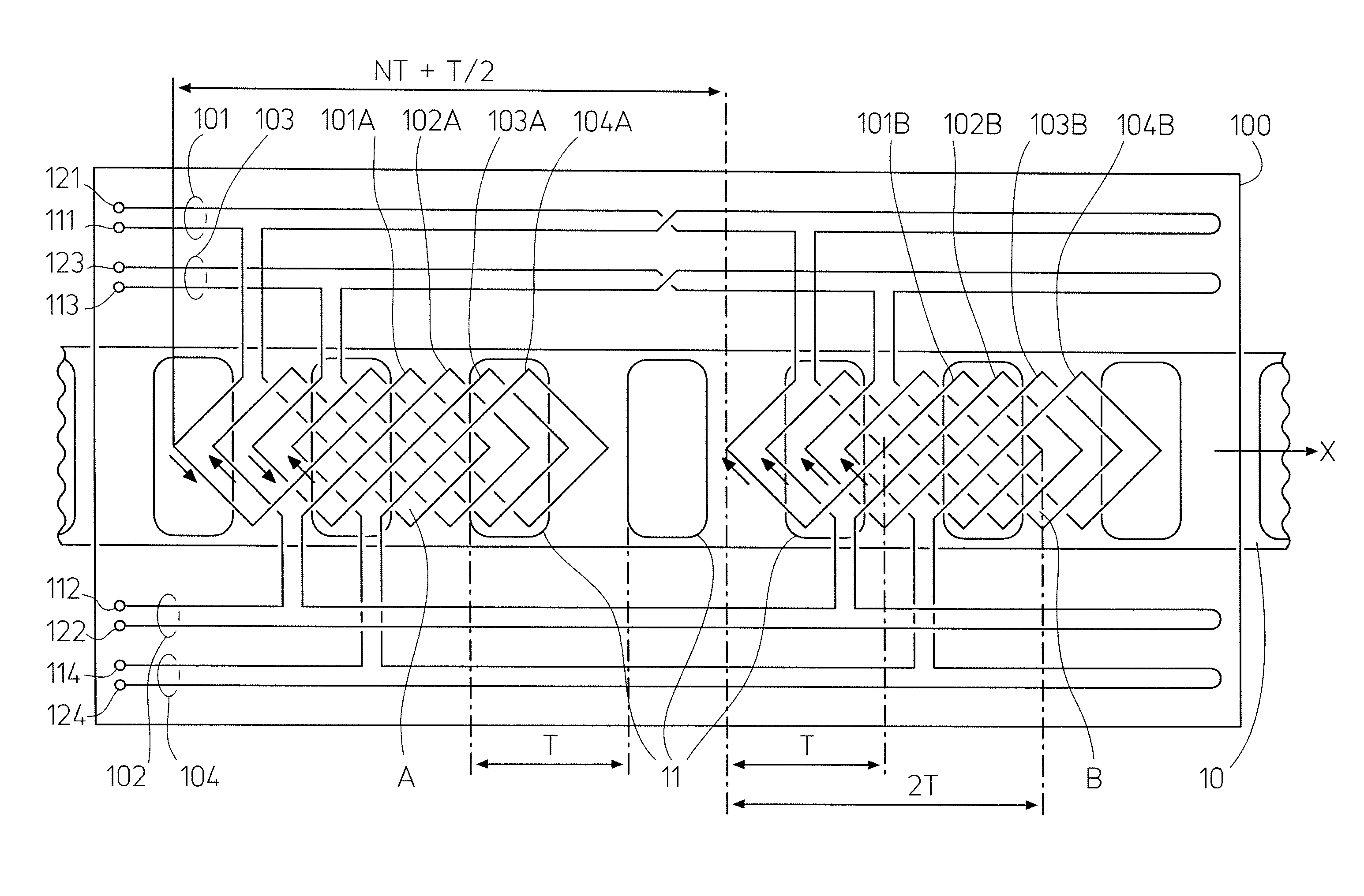
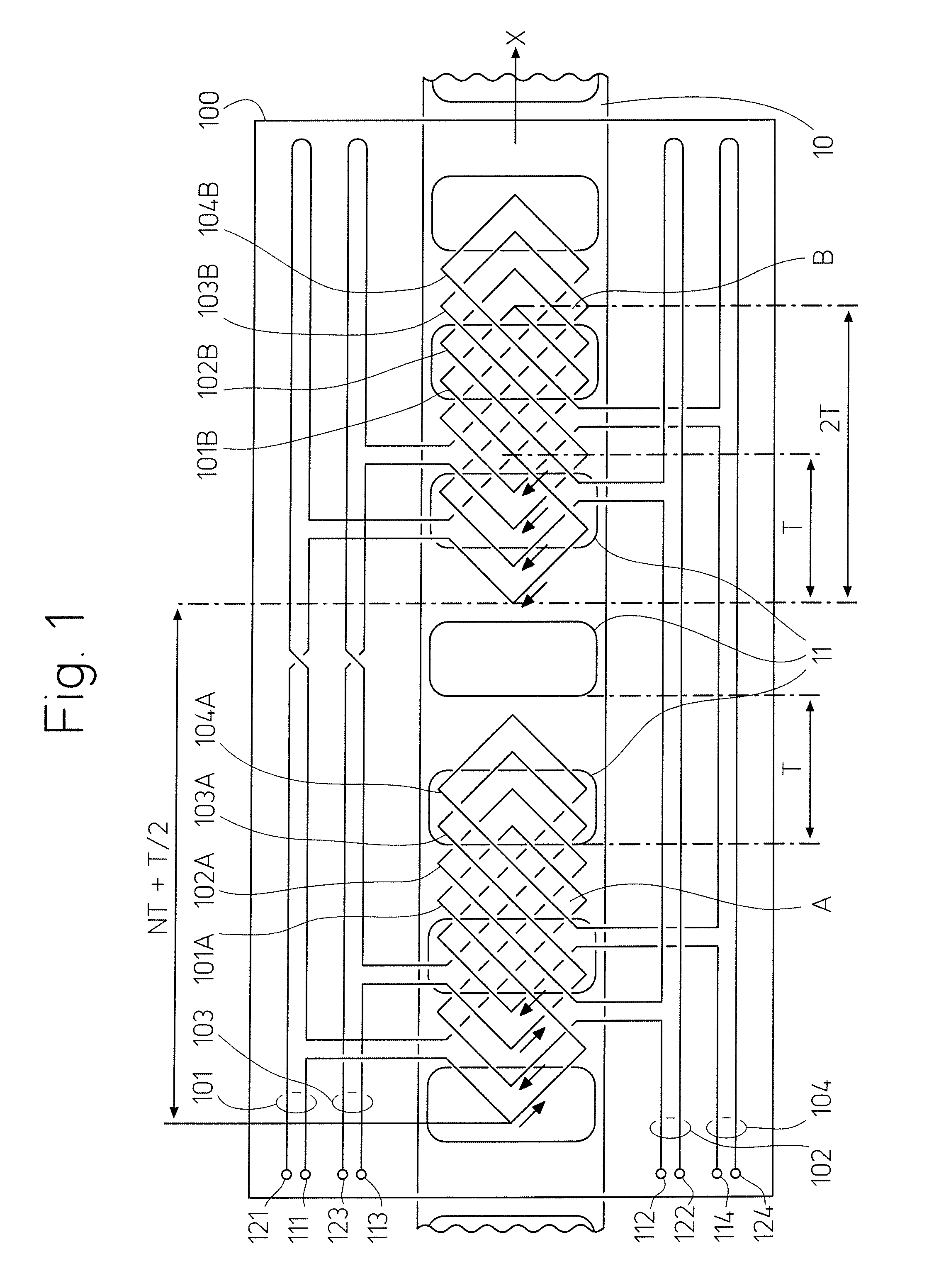
[0016]a sensor according to the invention is shown in FIG. 1. The sensor consists of a flat scale 10 relatively movable along a path x under a flat reading head 100 with four windings 101, 102, 103, 104 shown in transparency, as they are on or near the side facing the scale, i.e. under reading head 100 as seen from above. The scale 10 has a spatially periodic series of conducting screens 11, of spatial period T along path x, i.e. along the scale.

[0017]Each winding 101, 102, 103, 104 is divided in two separate identical winding elements facing the scale 10, respectively 101A and 101B, 102A and 102B, 103A and 103B, 104A and 10413. Winding elements 101A, 102A, 103A, 104A, shifted from each other by T / 4, are interlaced together in a first winding element pattern A, and winding elements 101B, 102B, 103B, 104B, shifted from each other by T / 4, are interlaced together in a second winding element pattern B, identical to the first. Pattern B is shifted from pattern A by NT+T / 2, N being an int...

second embodiment

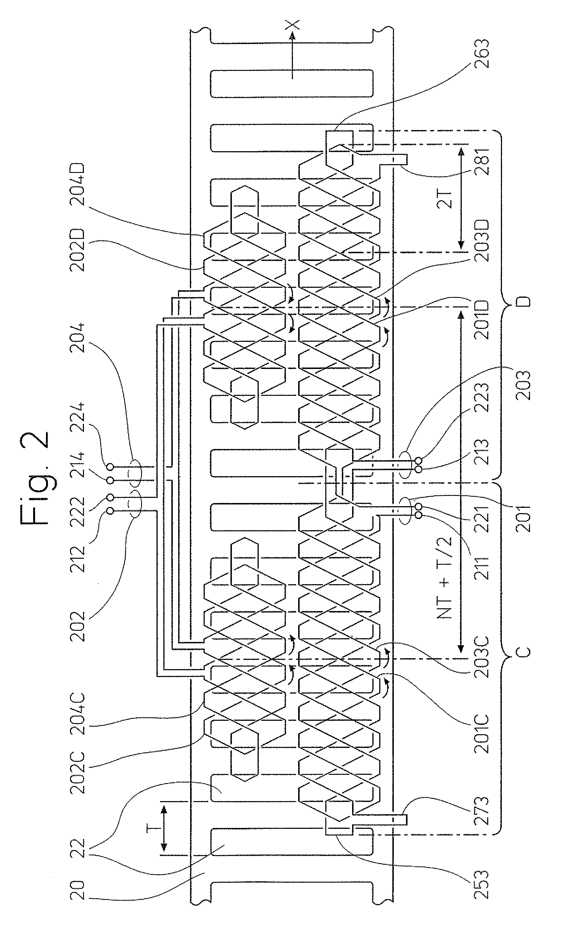
[0032]a sensor according to the invention is shown in FIG. 2. The sensor consists of a scale 20 movable along a path x under a reading head (outline not shown) with four windings 201, 202, 203, 204 lying on or near the side facing the scale. The flat ladder-like scale 20 is conducting and has a spatially periodic series of openings 22 with a spatial period T along the path x, i.e. along the scale.

[0033]Each winding 201, 202, 203, 204 is divided in two separate identical winding elements facing the scale 20, respectively winding elements 201C and 201D, winding elements 202C and 202D, winding elements 203C and 203D, and winding elements 204C and 204D. Winding elements 201C, 202C, 203C, 204C, shifted from each other along the scale by T / 4, are interlaced by pairs in a winding element pattern C, and winding elements 201D, 202D, 203D, 204D, shifted from each other along the scale by T / 4, are interlaced by pairs in a winding element pattern D identical to pattern C. Both patterns C and D ...


PUM

PropertyMeasurementUnit
drive currentaaaaaaaaaa
shapeaaaaaaaaaa
center-to-center distanceaaaaaaaaaa

Abstract

An inductive position sensor has a spatially periodic scale with a series of conducting or permeable features of pitch T and a reading head with drive windings and sense windings, facing the scale with a spatial period 2T along the scale. The windings are each divided in two identical winding elements,having the same relative location within two identical winding element patterns having a center-to-center distance along the scale of NT+T / 2, N being an integer, and connected so that the winding element polarities in each winding are either opposed for drive windings and the same for sense windings or the same for drive windings and opposed for sense windings. Thereby, direct couplings in both patterns cancel each other, while the spatially periodic signals coupled via the scale reinforce each other.

Description

BACKGROUND OF THE INVENTION[0001]This invention relates to an inductive position sensor, and more particularly to inductive position sensors having a relatively movable scale and reading head, the scale comprising a spatially periodic series of conducting or permeable features of spatial period T, and the reading head comprising drive and sense windings facing the scale with a spatially periodic configuration of spatial period T2 along the scale.[0002]In such sensors, the signal coupled from one winding to another via the scale's spatially periodic features varies sinusoidally with the reading head's position along the scale, its spatial period being equal to the scale's spatial period T. Measuring two or more such signals yields two or more mutually shifted sinusoidal functions, from which the reading head's position along the scale may be determined. Such sensors are simple, rugged and compact. External shielding is usually unnecessary, as their multi-polar windings are hardly sen...

Claims


Application Information

Patent Timeline
Patent Type & Authority Patents(United States)
IPC IPC(8): G01B7/14H01F5/00
CPCG01D5/202
Inventor MEYER, HANS ULRICH
Owner MELIUS
Why Eureka
Try Eureka