
Color filter array and method

a filter array and color filter technology, applied in the field of digital still camera or digital video camera system, can solve the problems of poor interpolation method, subject edge color error, etc., and achieve the effect of improving image quality and reducing image quality

Active Publication Date: 2010-01-26
TEXAS INSTR JAPAN
View PDF5 Cites 24 Cited by
  • Summary
  • Abstract
  • Description
  • Claims
  • Application Information

AI Technical Summary

Problems solved by technology

But simply averaging neighboring colors to interpolate missing colors causes faulty colors at subject edges, et cetera.
Much work has been performed to solve the problem (e.g., U.S. Pat. No. 5,506,619) but the results are unsatisfactory.
Therefore, a good interpolation method is still lacking for high quality images.

Method used


Image

  • Color filter array and method
  • Color filter array and method
  • Color filter array and method

Examples


Embodiment Construction

1. Overview

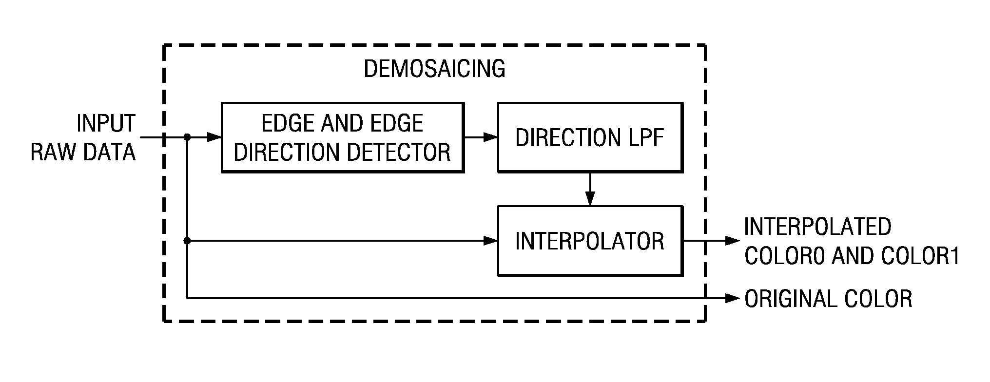
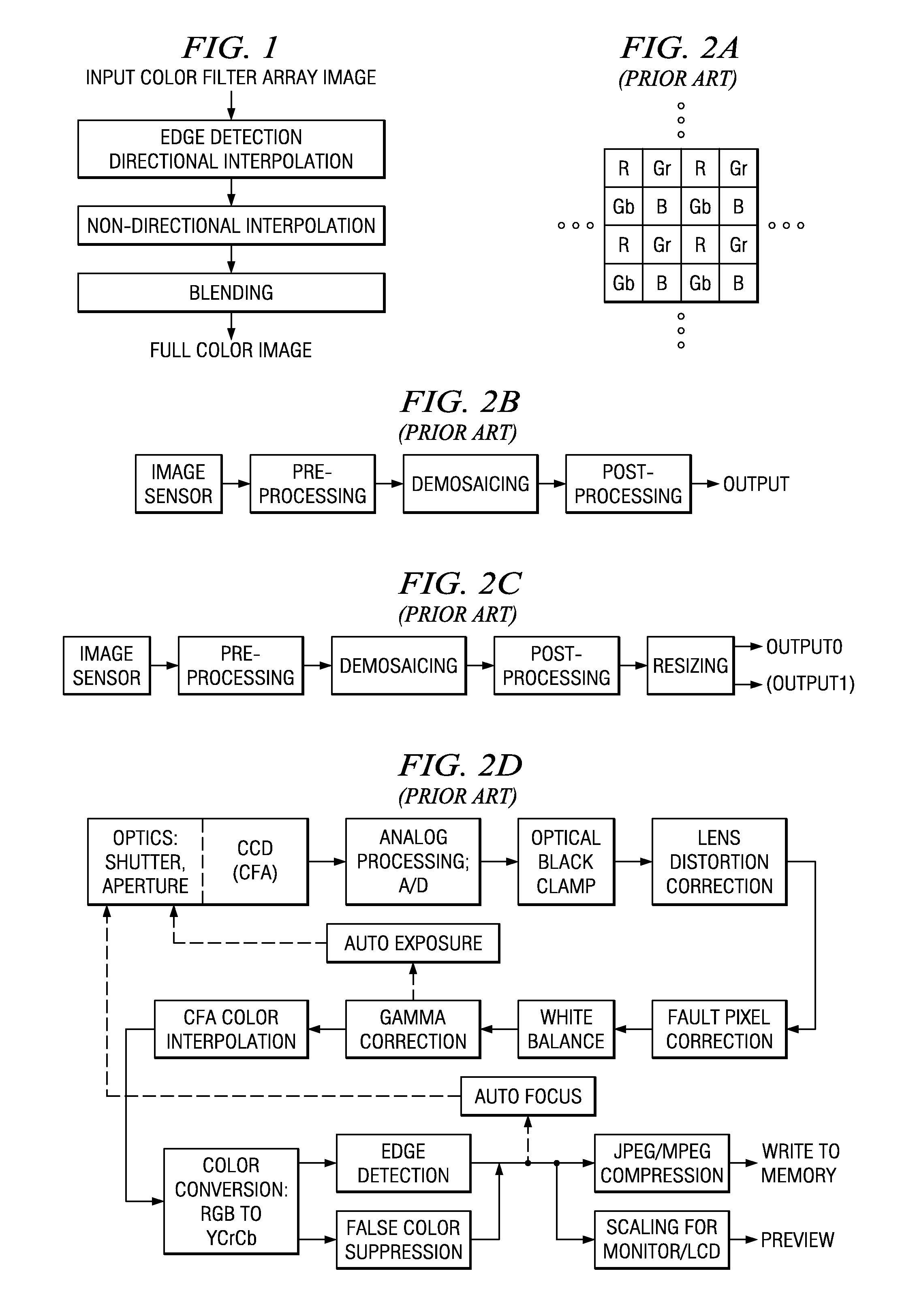
[0027]Preferred embodiment methods of color filter array interpolation (demosaicing) include blending directional and non-directional interpolations; see FIG. 1 flowchart and FIGS. 3a-3i functional blocks detailing the directional and non-directional interpolations and blending.

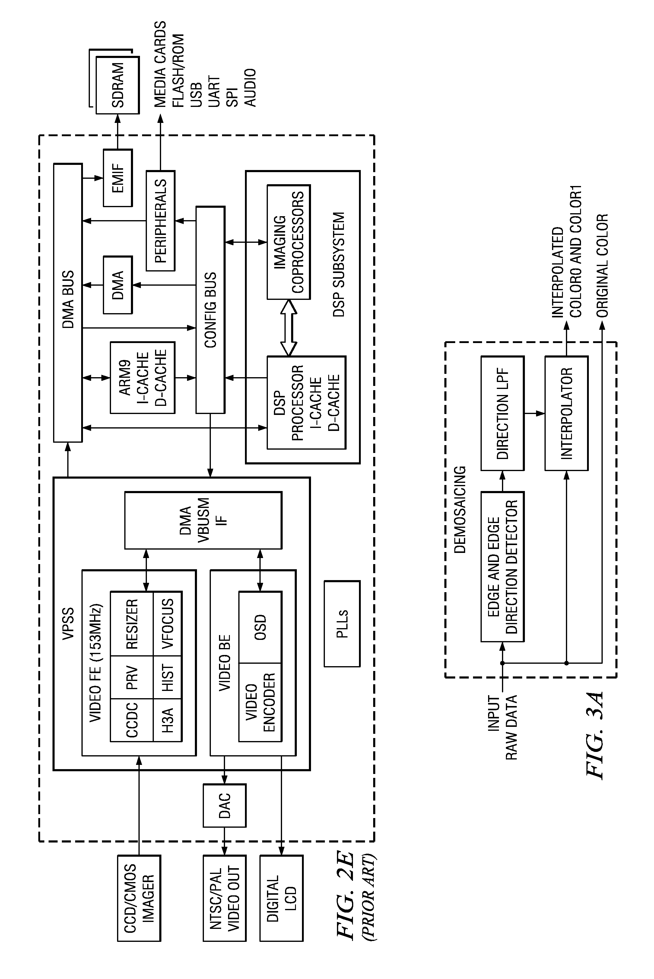
[0028]Preferred embodiment systems perform preferred embodiment methods with any of several types of hardware: digital signal processors (DSPs), general purpose programmable processors, application specific circuits, or systems on a chip (SoC) such as combinations of a DSP and a RISC processor together with various specialized programmable accelerators such as for FFTs and variable length coding (VLC). FIG. 2e illustrates a suitable processor. A stored program in an onboard or external (flash EEP) ROM or FRAM could implement the signal processing. Analog-to-digital converters and digital-to-analog converters can provide coupling to the real world, modulators and demodulators (plus antennas for air ...


PUM


Abstract

Color filter array demosaicing as is useful in digital cameras, still and video, using a single sensor includes blending of directional and non-directional interpolations. Directional interpolation uses edge detection with lowpass filtering with neighboring pixels for erroneous detection correction.

Description

CROSS-REFERENCE TO RELATED APPLICATIONS[0001]This application claims priority from provisional application No. 60 / 674,174, filed Apr. 22, 2005.BACKGROUND OF THE INVENTION[0002]The present invention is related to digital image processing, and more particularly, digital still camera or digital video camera systems which employ a single image sensor with a color filter array.[0003]In electronic color image systems, each image consists of a two-dimensional array of pixels and the full color of each pixel is represented by three color planes, usually red (R), green (G) and blue (B). Image light from a subject is converted to electric signals by a two dimensional array of photo-detectors, i.e., image sensor. To capture the information of the each color plane, three image sensors are used to detect light intensity of each color. But sometimes only one image sensor covered by a two-dimensional mosaic color filter array (CFA) is used for reducing cost, miniaturizing system, etc. The Bayer pa...

Claims


Application Information

Patent Timeline
IPC IPC(8): G06K9/00
CPCG06T3/4015
Inventor OTOBE, MASANORIYAMAUCHI, SATORUINAMORI, SHINRI
Owner TEXAS INSTR JAPAN
Learn More