
Shock absorber with integrated position sensor

a position sensor and shock absorber technology, applied in the field of shock absorbers, can solve the problems of increasing weight, increasing labor intensity, and increasing the difficulty of operators to adjust the suspension ride height at a proper level, and achieve the effect of easy adjustment of the suspension ride heigh

Active Publication Date: 2010-02-02
ARVIN TECH INC
View PDF20 Cites 36 Cited by
  • Summary
  • Abstract
  • Description
  • Claims
  • Application Information

AI Technical Summary

Problems solved by technology

One disadvantage with this system is that the mechanical linkage adds complexity, is labor intensive and increases weight.
Additionally, operators do not always set the ride height at a proper level based on vehicle application and / or payload.
One disadvantage with this configuration is that the additional components, i.e. accelerometers and displacement transducers, increase the cost of the suspension system.

Method used


Image

  • Shock absorber with integrated position sensor
  • Shock absorber with integrated position sensor
  • Shock absorber with integrated position sensor

Examples


Embodiment Construction

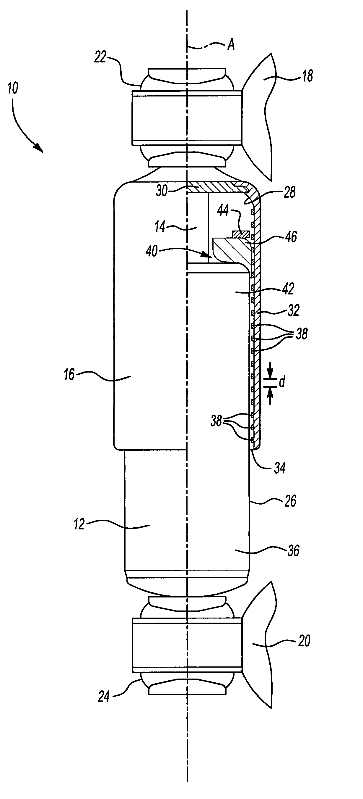
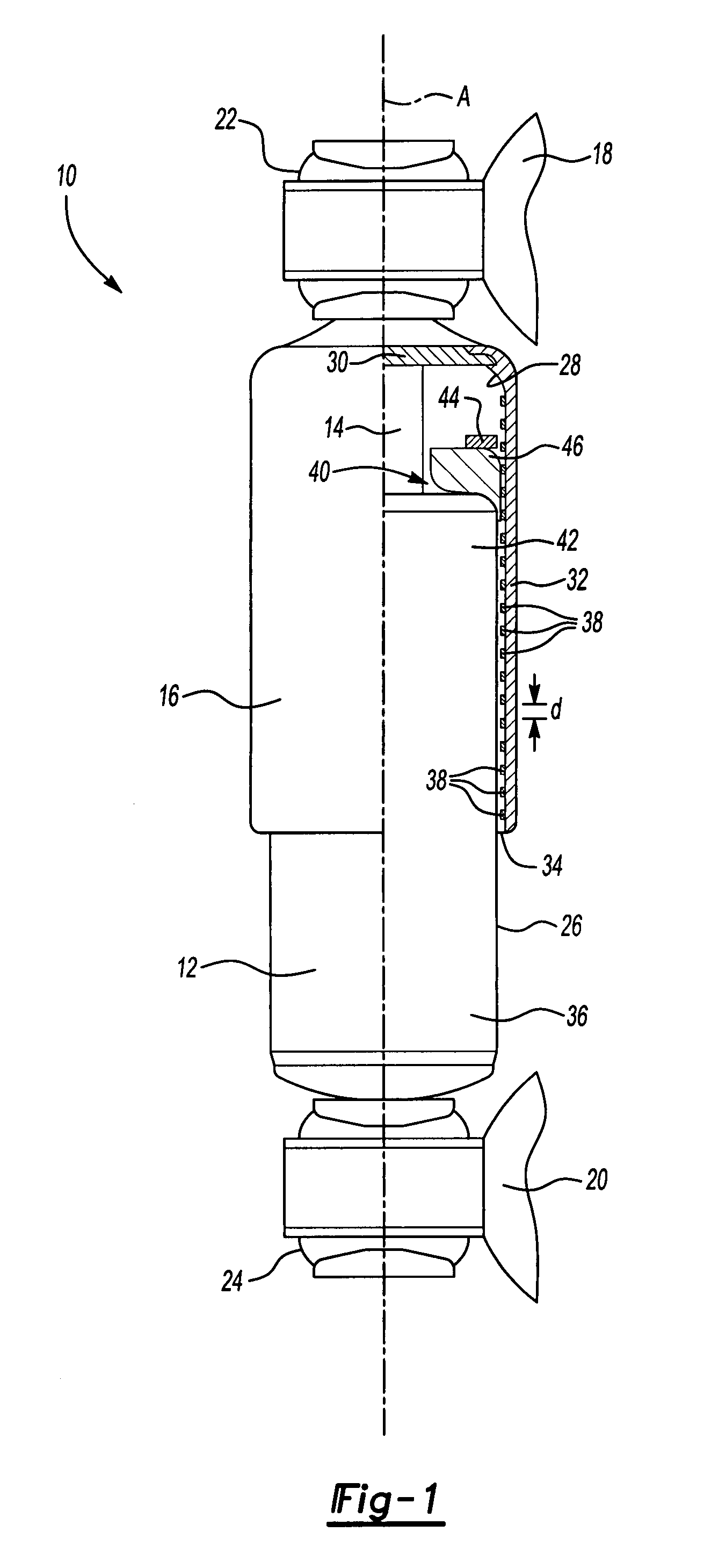
[0013]As shown in FIG. 1, a shock absorber 10 includes an outer shock body 12, a rod 14 that is movable relative to the shock body 12 along a rod axis A, and a dust tube 16 that protects the shock body 12. One of the rod 14 and the shock body 12 is attachable to a vehicle frame or chassis 18 and the other of the rod 14 and shock body 12 is attachable to a wheel or axle component 20. In the example shown, the rod 14 is attached to the vehicle chassis 18 via a first mounting bushing 22 and the shock body 12 is attached to an axle component 20 via a second mounting bushing 24. Thus, the shock body 12 moves with the axle component 20 and the dust tube 16 and rod 14 moves with the vehicle chassis 18. A reverse mounting configuration could also be used.

[0014]As known, the rod 14 extends into an interior of the shock body 12 and is coupled to a piston assembly (not shown). Operation of the shock absorber 10 to dampen road load inputs is known and will not be discussed in further detail.

[00...


PUM


Abstract

A shock absorber includes a dust tube that surrounds a shock body. The shock body is movable relative to the dust tube in response to road load inputs. A plurality of magnets is mounted to one of the dust tube and shock body, and a module is mounted to the other of the dust tube and shock body. The module interacts with the plurality of magnets to determine a position of the dust tube relative to a position of the shock body. This position information can be used to adjust suspension ride height as needed.

Description

TECHNICAL FIELD[0001]A shock absorber includes an integrated position sensor that is used to adjust suspension ride height.BACKGROUND OF THE INVENTION[0002]Air suspensions include leveling valves that can be adjusted to change a ride height of the air suspension. With current air suspensions, ride height is set by, and adjusted by, a mechanical linkage that is attached to the leveling valves. This mechanical linkage must be manually actuated by an operator to adjust ride height. One disadvantage with this system is that the mechanical linkage adds complexity, is labor intensive and increases weight. Additionally, operators do not always set the ride height at a proper level based on vehicle application and / or payload.[0003]Other types of suspensions systems, such as adaptive, semi-active, and active suspensions use accelerometers and / or displacement transducers to determine wheel position and wheel velocity. This information is then used to adjust right height as needed. One disadva...

Claims


Application Information

Patent Timeline
Patent Type & Authority Patents(United States)
IPC IPC(8): F16F15/03
CPCB60G17/01933F16F9/3292F16F9/38B60G2204/112B60G2400/252B60G2401/17
Inventor CUBALCHINI, JR., JOSEPH
Owner ARVIN TECH INC
Learn More