Operator seat for construction machine, and cab and construction machine including the same

a technology for operating seats and construction machines, applied in the field of operating seats for construction machines and cabs and construction machines including the same, can solve the problems of reducing the attractiveness, reducing the size of portions, and reducing the cooling effect of hydraulic oil stored in the hydraulic oil tank

a technology for operating seats and construction machines, applied in the field of operating seats for construction machines and cabs and construction machines including the same, can solve the problems of reducing the attractiveness, reducing the size of portions, and reducing the cooling effect of hydraulic oil stored in the hydraulic oil tank

US7654601B2Inactive Publication Date: 2010-02-02KOMATSU LTD

Image

  • Operator seat for construction machine, and cab and construction machine including the same
  • Operator seat for construction machine, and cab and construction machine including the same
  • Operator seat for construction machine, and cab and construction machine including the same

Examples


Embodiment Construction

Structure

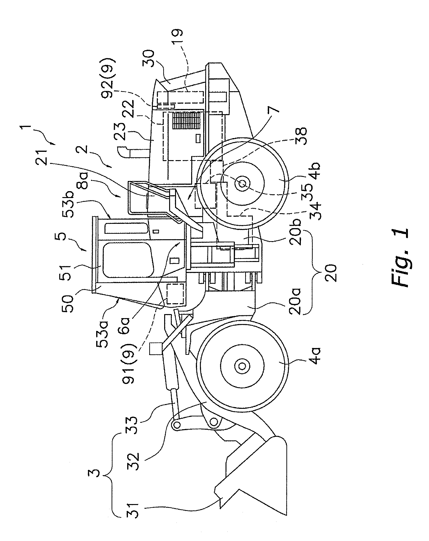
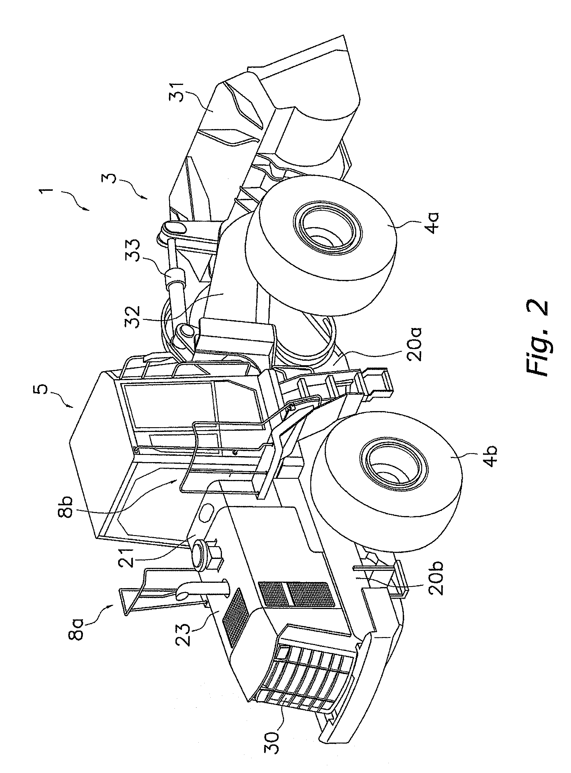
[0028]A left side view of a construction vehicle 1 of an embodiment of the present invention is shown in FIG. 1. This construction vehicle 1 is a wheel loader that is capable of propelling itself using the tires 4a, 4b and is capable of carrying out desired operations using working equipment 3. The construction vehicle 1 mainly includes a vehicle body 2, the tires 4a, 4b, the working equipment 3, a operator cab 5, an air conditioning equipment 9, side steps 6a, 6b (refer to FIG. 6), a fender 7, and bars 8a, 8b (refer to FIG. 6).

Vehicle Body 2

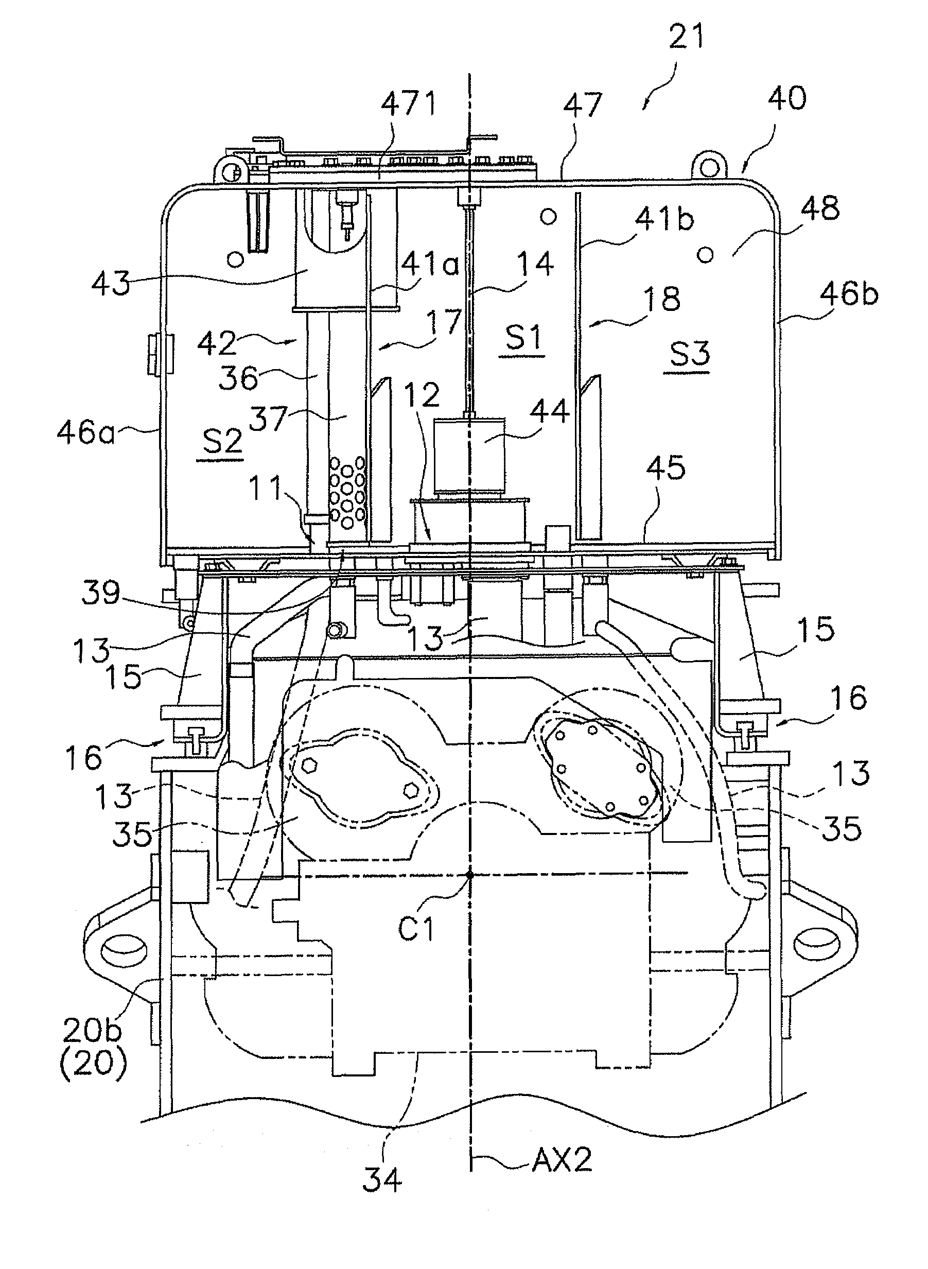
[0029]The vehicle body 2 has a vehicle frame 20, a hydraulic oil tank 21, an engine 22, a transmission 34, a torque converter 38, a hydraulic oil pump 35, and an engine cover 23, etc.

Vehicle Frame 20

[0030]The vehicle frame 20 has a front frame 20a disposed to the front side, and a rear frame 20b disposed to the rear side. The front frame 20a and the rear frame 20b are coupled in a manner enabling rocking in a lateral direction at a cent...


PUM


Abstract

A construction vehicle includes vehicle frames, an operator cab, a hydraulic oil tank, and engine, and an engine cover. The operator cab is mounted on the vehicle frames. The hydraulic oil tank is disposed to the rear of the operator cab and stores hydraulic oil. The engine is disposed to the rear of the hydraulic oil tank. The engine cover is a member that covers the engine. A rear face of the hydraulic oil tank and a front face of the engine cover are the same size in a widthwise direction. A rear end of an upper face of the hydraulic oil tank is positioned at the same height as a front end of the upper face of the engine cover. The upper face and side faces of the hydraulic oil tank are exposed to outside.

Description

CROSS-REFERENCE TO RELATED APPLICATIONS[0001]This U.S. National stage application claims priority under 35 U.S.C. ยง119(a) to Japanese Patent Application No. 2005-365297, filed in Japan on Dec. 19, 2005. The entire disclosure of Japanese Patent Application No. 2005-365297 is hereby incorporated herein by reference.TECHNICAL FIELD[0002]The present invention relates to a construction vehicle.BACKGROUND ART[0003]A hydraulic oil tank for storing hydraulic oil such as hydraulic oil supplied to a hydraulic oil pump is provided at a construction vehicle. This hydraulic oil tank is provided in the vicinity of a side end of a vehicle frame. For example, in a construction vehicle disclosed in Japanese Patent Application Laid-open No. 2002-97666, a hydraulic oil tank is provided in the vicinity of a side end of a vehicle frame on a working equipment side. A battery storage case is disposed to the front of the hydraulic oil tank and an engine room is disposed to the rear of the hydraulic oil tan...

Claims


Application Information

Patent Timeline
02 Feb 2010
Publication
US7654601B2
IPC
B60N2/14
CPC
B60N2/14; B60N2/24; B60N2/4606; B60N2/4693; E02F9/0833; E02F9/163; E02F9/2004; B60N2/753
Inventors
SPELLMEYER, GUNNAR; WELLER, BIRGIT