
Progressive addition lens operating in combination with a multi-order diffractive optic

a diffractive optic and progressive addition technology, applied in the field of multi-focal lenses, can solve the problems of serious vision compromise, present problems, and use of pals, and achieve the effect of reducing chromatic aberration and chromatic aberration

Inactive Publication Date: 2010-02-02
MITSUI CHEM INC
View PDF3 Cites 26 Cited by
  • Summary
  • Abstract
  • Description
  • Claims
  • Application Information

AI Technical Summary

Benefits of technology

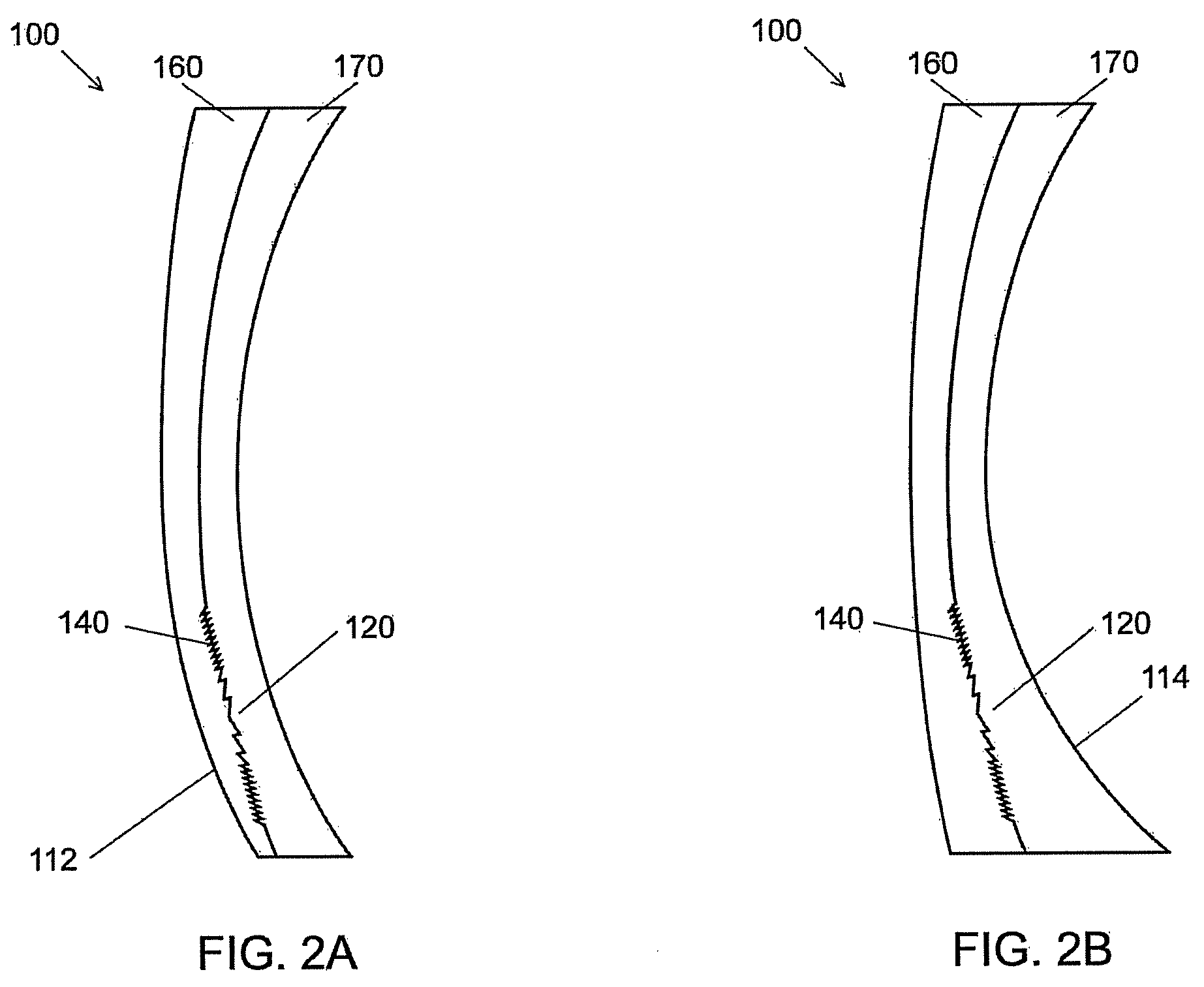
The invention is a multi-focal spectacle lens that can correct vision for far distance, intermediate distance, and near distance. It includes a progressive addition surface and a multi-order diffractive surface relief structure that reduces chromatic aberrations. The combination of these two features provides an overall progression of optical add power. The lens has a front piece and a back piece with the diffractive lens structure positioned between them. The front or rear surface may also have a portion of a progressive addition surface that adds to the optical add power. This lens design provides improved vision correction for a wide range of distances.

Problems solved by technology

Using PALs, however, presents problems.
One problem is that PALs have serious vision compromises that include, but are not limited to, unwanted astigmatism, distortion, and perceptual blur, especially for large near distance corrections (large near add powers).
In addition, many wearers of PALs experience an unpleasant effect known as visual motion (often referred to as “swim”) due to the distortion that exists in the lenses.
While the use of a diffractive optical element in combination with a low power PAL may considerably reduce visual distortion of the PAL (especially for large total add powers), the diffractive lens may itself introduce new unwanted effects, e.g., noticeable chromatic aberrations in higher prescriptions due to the highly dispersive nature of diffractive optical elements.

Method used


Image

  • Progressive addition lens operating in combination with a multi-order diffractive optic
  • Progressive addition lens operating in combination with a multi-order diffractive optic
  • Progressive addition lens operating in combination with a multi-order diffractive optic

Examples


Embodiment Construction

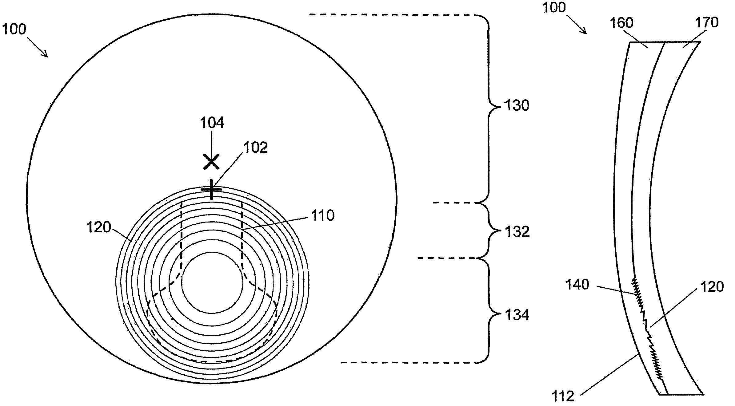
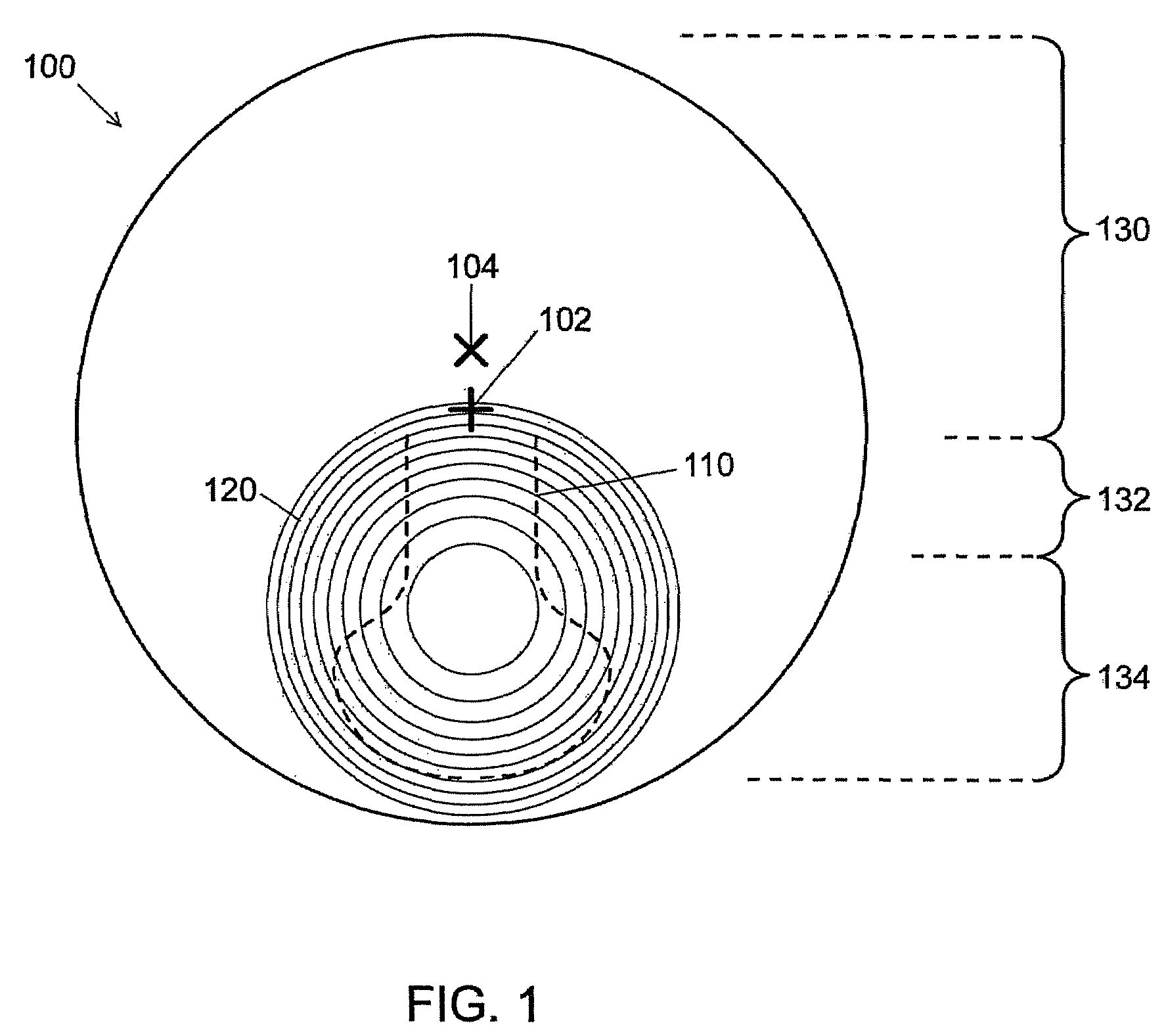
[0017]FIG. 1 shows a front view of a lens 100 having a progressive addition region 110 and a diffractive addition region 120.

[0018]The progressive addition region 110 is a low add power PAL designed to provide a wearer with an optical power less than the wearer's needed near distance optical power correction. For example, the add power of the PAL may be 50% of the required near distance optical power correction.

[0019]The diffractive addition region 120 is in optical communication with the progressive addition region. The diffractive addition region at least partially, and preferably largely, overlaps the progressive addition region. When used with the progressive addition region, the diffractive addition region provides the remaining optical power to provide the wearer's total needed near distance optical power correction. The diffractive addition region may be a multi-order diffractive (MOD) lens, e.g., as described by Faklis et al. (U.S. Pat. No. 5,589,982) and Morris et al. (U.S....


PUM


Abstract

A multi-focal spectacle lens is presented having far distance, intermediate distance, and near distance vision correction, in which the lens includes a progressive addition surface with a progression of optical power. The lens further includes a multi-order diffractive surface relief structure with an optical add power. The multi-order diffractive structure reduces chromatic aberration as compared to a conventional diffractive structure of equivalent optical power. The lens may also include a wavefront splitting device diffractive structure for generating multiple optical powers simultaneously. When the progressive addition surface and the multi-order diffractive surface relief structure are in optical communication an overall progression of optical add power may be provided by the combination of the progressive addition surface with the multi-order surface relief diffractive structure.

Description

CROSS REFERENCE TO RELATED APPLICATIONS[0001]This application claims priority from and incorporates by reference in its entirety the following provisional application:[0002]U.S. Ser. No. 60 / 924,344 filed on May 10, 2007 and entitled “Multi-focal progressive addition spectacle lens operating in conjunction with a multi-order diffractive optical device”.BACKGROUND OF THE INVENTION[0003]A multi-focal lens typically has multiple regions each having a different optical power. The transition between the regions of different optical power may be either abrupt, as is the case for bifocal and trifocal lenses, or smooth and continuous, as is the case with Progressive Addition Lenses (PALs). Progressive Addition Lenses are a type of multi-focal lens that comprise a gradient of continuously increasing positive optical power from the beginning of a far distance viewing zone of the lens to a near distance viewing zone in the lower portion of the lens. This progression of optical power generally s...

Claims


Application Information

Patent Timeline
Patent Type & Authority Patents(United States)
IPC IPC(8): G02C7/06
CPCG02C7/061G02C2202/16G02C2202/20
Inventor BLUM, RONALD D.KOKONASKI, WILLIAMHADDOCK, JOSHUA N.
Owner MITSUI CHEM INC
Learn More