Supercharge Your Innovation With Domain-Expert AI Agents!

Light assembly for an image projector

a technology of image projector and assembly, which is applied in the direction of lighting and heating apparatus, instruments, and semiconductor/solid-state device details, etc., can solve the problem of large size of conventional image projector

Active Publication Date: 2010-02-02
COMPAL ELECTRONICS INC
View PDF5 Cites 4 Cited by
  • Summary
  • Abstract
  • Description
  • Claims
  • Application Information

AI Technical Summary

Benefits of technology

The solution effectively dissipates heat generated by the light-emitting device while reducing the overall size of the projector by optimizing the use of space, allowing for a more compact projector design.

Problems solved by technology

The aforementioned conventional image projector is disadvantageous in that the fans occupy a relatively large space in the conventional image projector, thereby resulting in a larger size for the conventional image projector.

Method used


Image

  • Light assembly for an image projector
  • Light assembly for an image projector
  • Light assembly for an image projector

Examples


Embodiment Construction

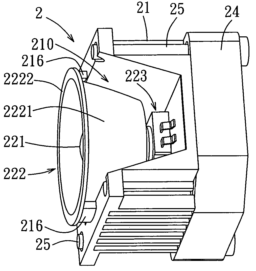
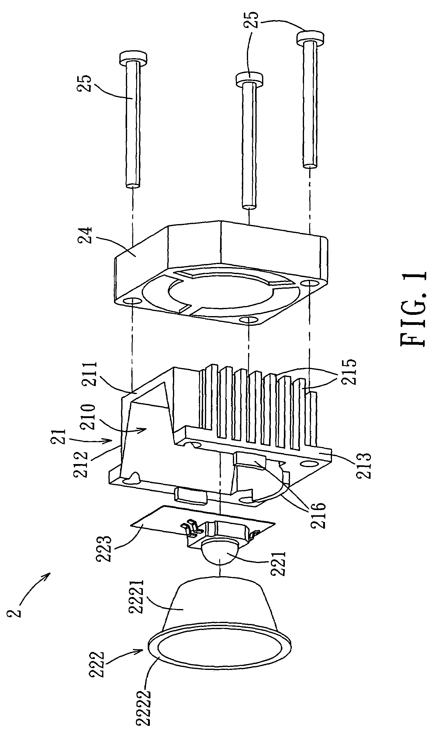
[0014]Referring to FIGS. 1 and 2, the preferred embodiment of a light assembly 2 according to this invention is shown to include a heat-dissipating device 21, a light-emitting device 221, and a reflector222.

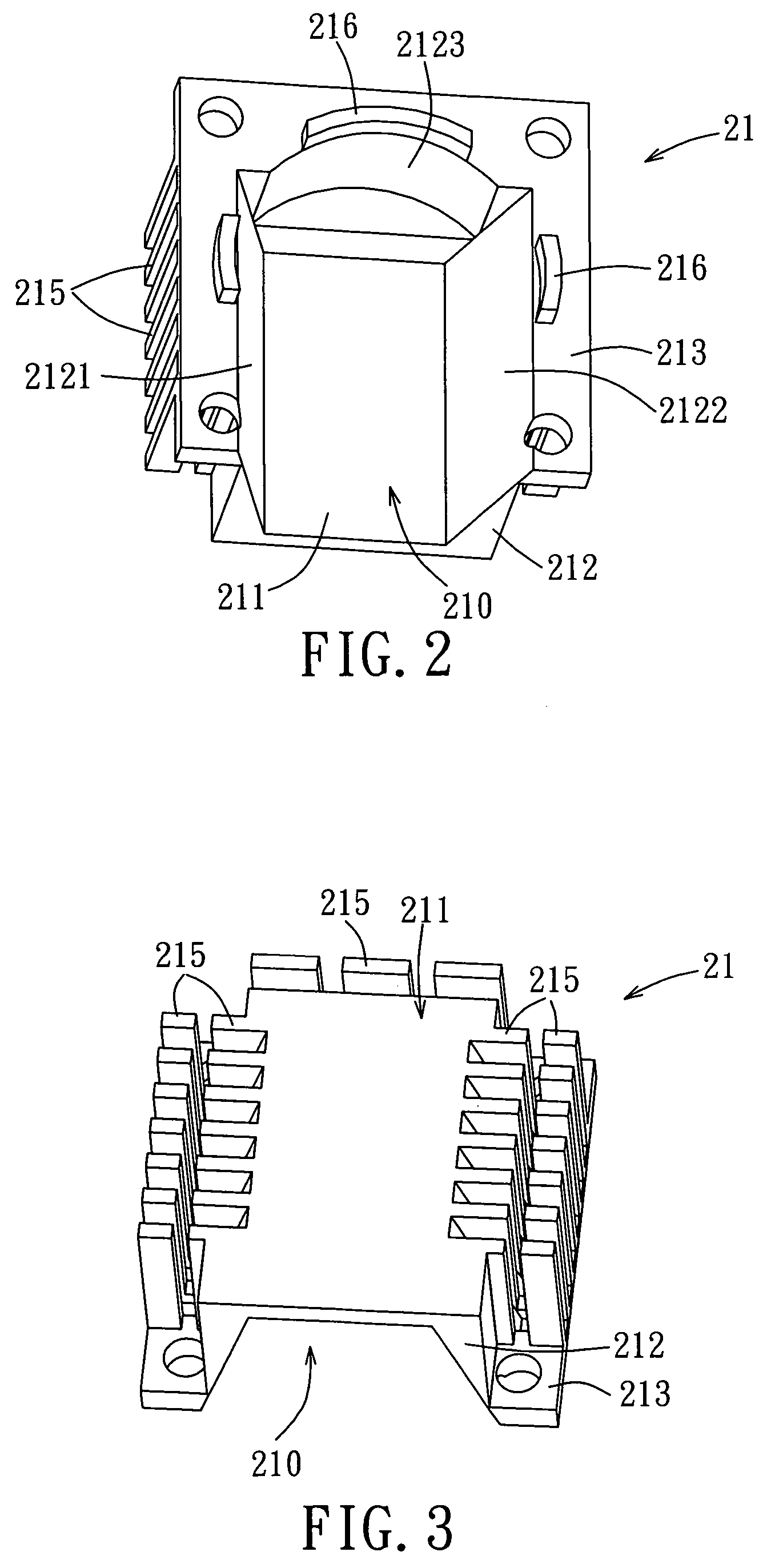
[0015]The heat-dissipating device 21 includes a thermally conductive base 211, a thermally conductive peripheral wall 212, and a plurality of thermally conductive fins 215.

[0016]The thermally conductive base 211 of the heat-dissipating device 21 is generally rectangular in shape, and has opposite first and second sides and opposite third and fourth sides.

[0017]The thermally conductive peripheral wall 212 of the heat-dissipating device 21 cooperates with the thermally conductive base 211 of the heat-dissipating device 21 to define an accommodating space 210. In this embodiment, the thermally conductive peripheral wall 212 of the heat-dissipating device 21 includes first, second, and third wall parts 2121, 2122, 2123 that extend respectively from the first, second, and third sides ...


PUM


Abstract

A light assembly includes a heat-dissipating device, a light-emitting device, and a reflector. The heat-dissipating device defines an accommodating space. The light-emitting device is disposed in the accommodating space. The reflector serves to reflect light emitted by the light-emitting device, extends into the accommodating space, and surrounds the light-emitting device.

Description

BACKGROUND OF THE INVENTION[0001]1. Field of the Invention[0002]The invention relates to a light assembly, more particularly to a light assembly for an image projector.[0003]2. Description of the Related Art[0004]A conventional image projector includes a bulb, and a plurality of fans for dissipating heat generated by the bulb.[0005]The aforementioned conventional image projector is disadvantageous in that the fans occupy a relatively large space in the conventional image projector, thereby resulting in a larger size for the conventional image projector.SUMMARY OF THE INVENTION[0006]Therefore, the object of the present invention is to provide a light assembly fro an image projector that can overcome the aforesaid drawback associated with the prior art.[0007]According to the present invention, a light assembly for an image projector comprises a heat-dissipating device, a light-emitting device, and a reflector. The heat-dissipating device includes a thermally conductive base, a thermal...

Claims


Application Information

Patent Timeline
Patent Type & Authority Patents(United States)
IPC IPC(8): G03B21/16F28F1/30F28F7/00G03B21/28H01L23/34
CPCF21V29/004F21V29/763F21V29/75G03B21/16F21Y2101/02F21V29/74F21Y2115/10
Inventor KO, SHIN-BIN
Owner COMPAL ELECTRONICS INC
Features
  • R&D
  • Intellectual Property
  • Life Sciences
  • Materials
  • Tech Scout
  • Unparalleled Data Quality
  • Higher Quality Content
  • 60% Fewer Hallucinations
Learn More