Cyclone assembly and method for increasing or decreasing flow capacity of a cyclone separator in use

a technology of cyclone separator and assembly method, which is applied in the direction of water cleaning, separation process, borehole/well accessories, etc., can solve the problem that the system is not practicable when considering sub-sea processing

Active Publication Date: 2010-02-02
CAMERSON INT CORP
View PDF14 Cites 3 Cited by
  • Summary
  • Abstract
  • Description
  • Claims
  • Application Information

AI Technical Summary

Benefits of technology

[0054]The fluid flow capacity reduction and pressure increase are due to the reduction of cross-sectional area of the operative chamber of the cyclone. If the differential pressure across the inlet and outlet of the separator were to decrease or increase, without a change of liner (ie cross sectional area of the operative chamber) then a corresponding respective decrease or increase in flowrate would be expected. It is an advantage of the invention, that even with a decrease in the differential pressure, an increased flowrate can be achieved, by movement of the inner cyclone liner to the inoperative position.
, that even with a decrease in the differential pressure, an increased flowrate can be achieved, by movement of the inner cyclone liner to the inoperative position.

Problems solved by technology

Some typical problems associated with downstream processing are:Wear on valves, particularly choke pressure control valvesDrop out of solids in processing vessels such as three phase separatorsWear on pumps and rotating equipmentThe management of separated solids on the seabed following sub-sea processingDisposal of solids, which are contaminated with oil offshore.
Whereas these systems have had some success to date onshore and on topsides offshore, these systems are not practicable when considering sub-sea processing, because the retrieval of a cyclone vessel for maintenance and / or the use of divers in deep sea areas are not viable.

Method used


Image

  • Cyclone assembly and method for increasing or decreasing flow capacity of a cyclone separator in use
  • Cyclone assembly and method for increasing or decreasing flow capacity of a cyclone separator in use
  • Cyclone assembly and method for increasing or decreasing flow capacity of a cyclone separator in use

Examples


Embodiment Construction

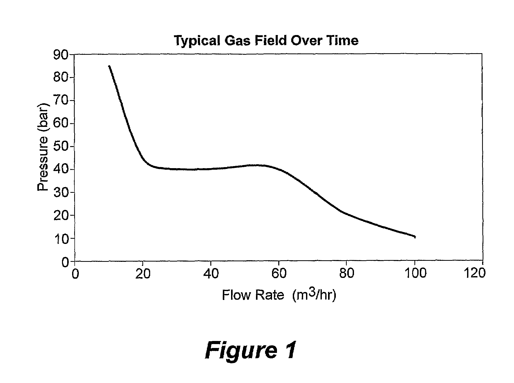
[0061]Referring firstly to FIG. 1, in a typical gas field, the flow rate to be passed through a cyclone separator, during the course of the life of the gas field, may increase from 10 m3 / hr to 100 m3 / hr. The pressure drop associated with such an increased flow rate is approximately from 85 bar down to 10 bar. It can therefore be seen that a cyclone separator may be required to operate over a flow rate range of 90 m3 / hr, whilst maintaining efficient separation.

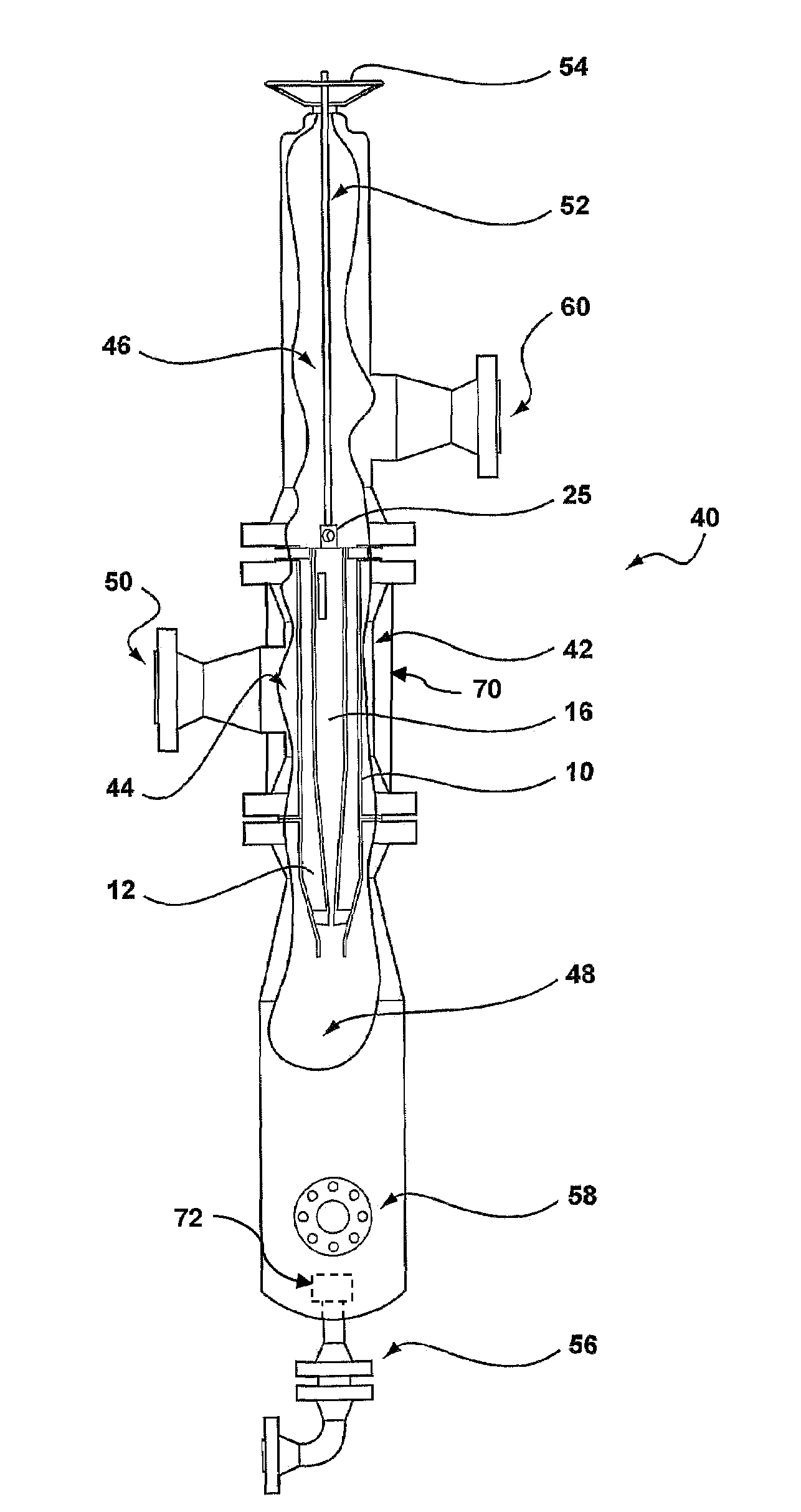
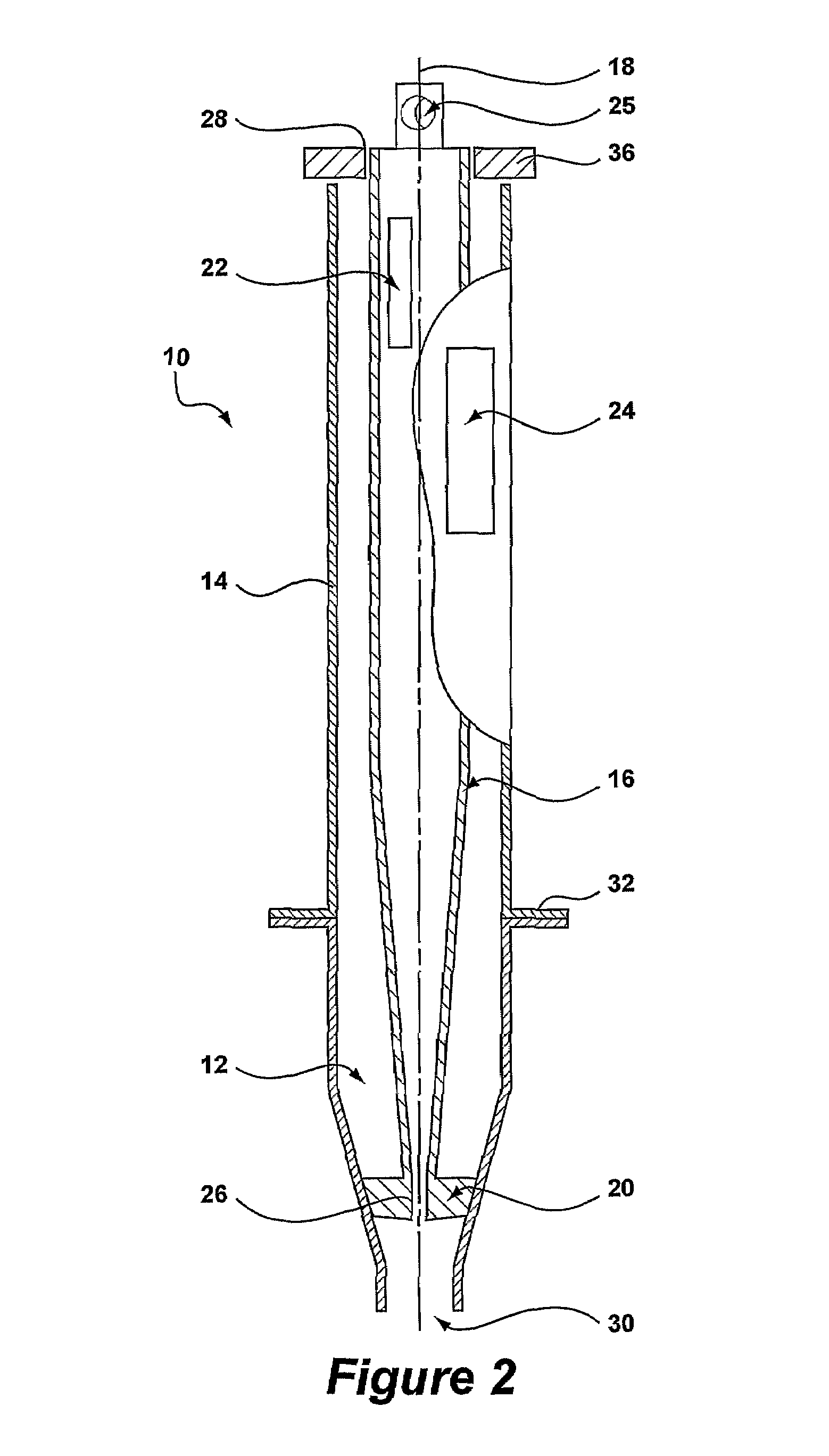
[0062]Referring to FIG. 2, a cyclone assembly is indicated generally at 10 and comprises a cyclone chamber 12, formed by an outer cyclone liner 14, and an inner cyclone liner 16. The inner cyclone liner 16 is adapted to be displaced along a longitudinal axis 18 of the outer cyclone liner 14 between an operative position, as viewed in FIGS. 2 and 3, and inoperative position, as viewed in FIG. 4, and explained further below.

[0063]A seal collar 20 is provided at a lower end of the inner cyclone liner 16. The seal collar 20 is inte...


PUM

PropertyMeasurementUnit
pressureaaaaaaaaaa
densityaaaaaaaaaa
flow rateaaaaaaaaaa

Abstract

A cyclone separator (40) includes a housing (42), in which a cyclone assembly (10) is contained. The housing (42) has an inflow chamber (44), an overflow chamber (46) and a discharge chamber (48). The cyclone assembly (10) has an inner cyclone liner (16) positioned concentrically within a cyclone chamber (12). A displacement means (52) is provided for displacing the inner cyclone liner (16) axially from an operative position in the cyclone chamber (12) to an inoperative position in the overflow chamber (46) of the housing (42). The cyclone chamber (12) has a larger internal diameter than the inner cyclone liner (16), therefore, when the inner cyclone liner is moved to the inoperative position, the flowrate through the cyclone assembly is increased.

Description

[0001]The present invention relates to a cyclone assembly and method for increasing or decreasing the flow capacity of a cyclone separator in use.BACKGROUND[0002]It has been known for some time that the management of solid particles, for example, sands, asphaltenes, clays, drill cuttings, and scale particles, discharged from hydrocarbon producing wells, has an important impact on downstream processing equipment. Some typical problems associated with downstream processing are:[0003]Wear on valves, particularly choke pressure control valves[0004]Drop out of solids in processing vessels such as three phase separators[0005]Wear on pumps and rotating equipment[0006]The management of separated solids on the seabed following sub-sea processing[0007]Disposal of solids, which are contaminated with oil offshore.[0008]With the advent of directional drilling, which is used to seek out and produce ever more recoverable hydrocarbons from old or marginal reservoirs, and the use of lateral completi...

Claims


Application Information

Patent Timeline
Patent Type & Authority Patents(United States)
IPC IPC(8): B01D45/00B01D45/12B04C5/08B04C5/103B04C5/20B04C5/24B04C5/28B04C11/00E21B21/06
CPCB04C5/08B04C5/103B04C5/20B04C5/24B04C11/00E21B21/065B04C1/00B04C3/00
Inventor PARKINSON, DAVID JOHN
Owner CAMERSON INT CORP
Why Eureka
Try Eureka