
Lens apparatus and image pickup apparatus

a technology of image pickup and lens barrel, which is applied in the direction of bearings, shafts and bearings, bearings, etc., can solve the problems of difficult miniaturization of the whole image pickup apparatus, large magnetic loss from a standpoint of circuit efficiency of the magnetic circuit, and unavoidable projection of a part of the lens barrel or the outer shape of the lens barrel, etc., to achieve the effect of simple arrangemen

Inactive Publication Date: 2010-02-02
SONY CORP
View PDF9 Cites 8 Cited by
  • Summary
  • Abstract
  • Description
  • Claims
  • Application Information

AI Technical Summary

Benefits of technology

The present invention provides a lens apparatus and an image pickup apparatus that can reliably and smoothly move a plurality of movable lens-barrels straight. This is achieved by a small lens apparatus that can be driven linearly and an image pickup apparatus including such lens apparatus. The lens apparatus includes a fixed lens-barrel with guide grooves and movable lens-barrels with corresponding guide grooves that can move independently. The movable lens-barrels are supported by rolling elements that allow them to move smoothly. The small lens apparatus and image pickup apparatus can provide a compact and efficient solution for optical zooming and image stabilization.

Problems solved by technology

In such case, it is unavoidable that a part of the lens-barrel is projected or that the outer shape of the lens-barrel becomes angular.
As a consequence, a part of the lens-barrel is unavoidably increased in thickness and hence it has been difficult to make the lens-barrel become cylinder with a small diameter, thereby making it difficult to miniaturize the whole of the image pickup apparatus.
Further, since most of the lens-barrel uses a ring-like coil having a rectangular shape as a coil and the effective portion of the ring-like coil as the magnetic circuit is only one side of the rectangular, it is inevitable that a magnetic loss becomes large from a standpoint of circuit efficiency of the magnetic circuit.
As a result, the lens-barrel was increased in thickness, the whole of the apparatus was increased in size unavoidably and driving efficiency was not satisfactory.
Accordingly, it has been difficult to collapse the collapsible type lens apparatus by a linear motor.
Furthermore, when the collapsible type lens apparatus is provided with the gear arrangement or motors are separately mounted on the collapsible type lens apparatus, it is unavoidable that the outer shape of the lens-barrel of the lens is increased in thickness.
As a result, the whole of the collapsible type lens apparatus might not be miniaturized and decreased in diameter as one wants it to be.
In the lens apparatus according to the related art, it has been difficult to miniaturize the lens-barrel of the lens while a plurality of lens holding frames is being made movable.
To this end, it is unavoidable that the whole of the lens apparatus becomes large in size.
Therefore, it was difficult to miniaturize the whole of the lens apparatus.

Method used


Image

  • Lens apparatus and image pickup apparatus
  • Lens apparatus and image pickup apparatus
  • Lens apparatus and image pickup apparatus

Examples


first embodiment

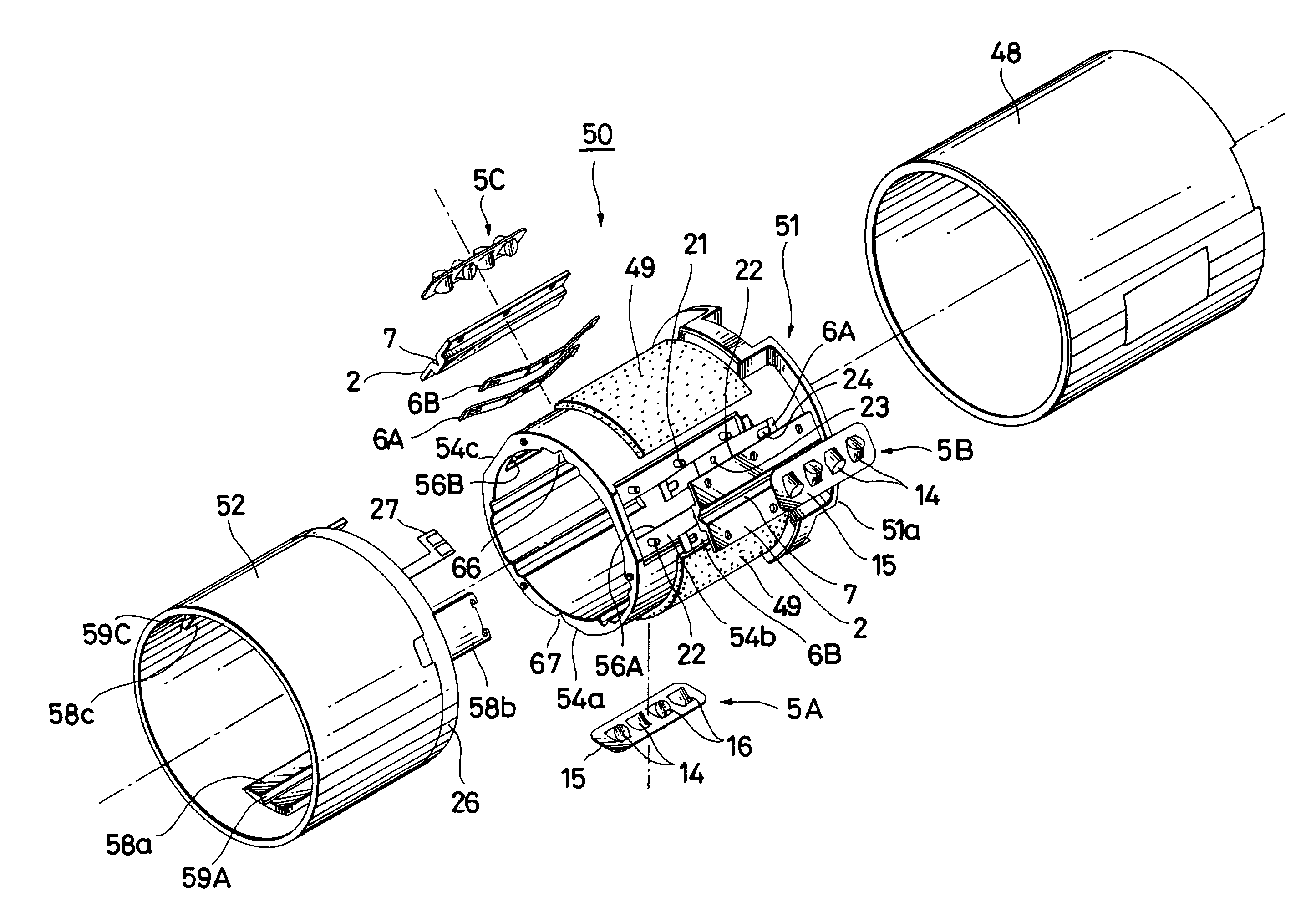
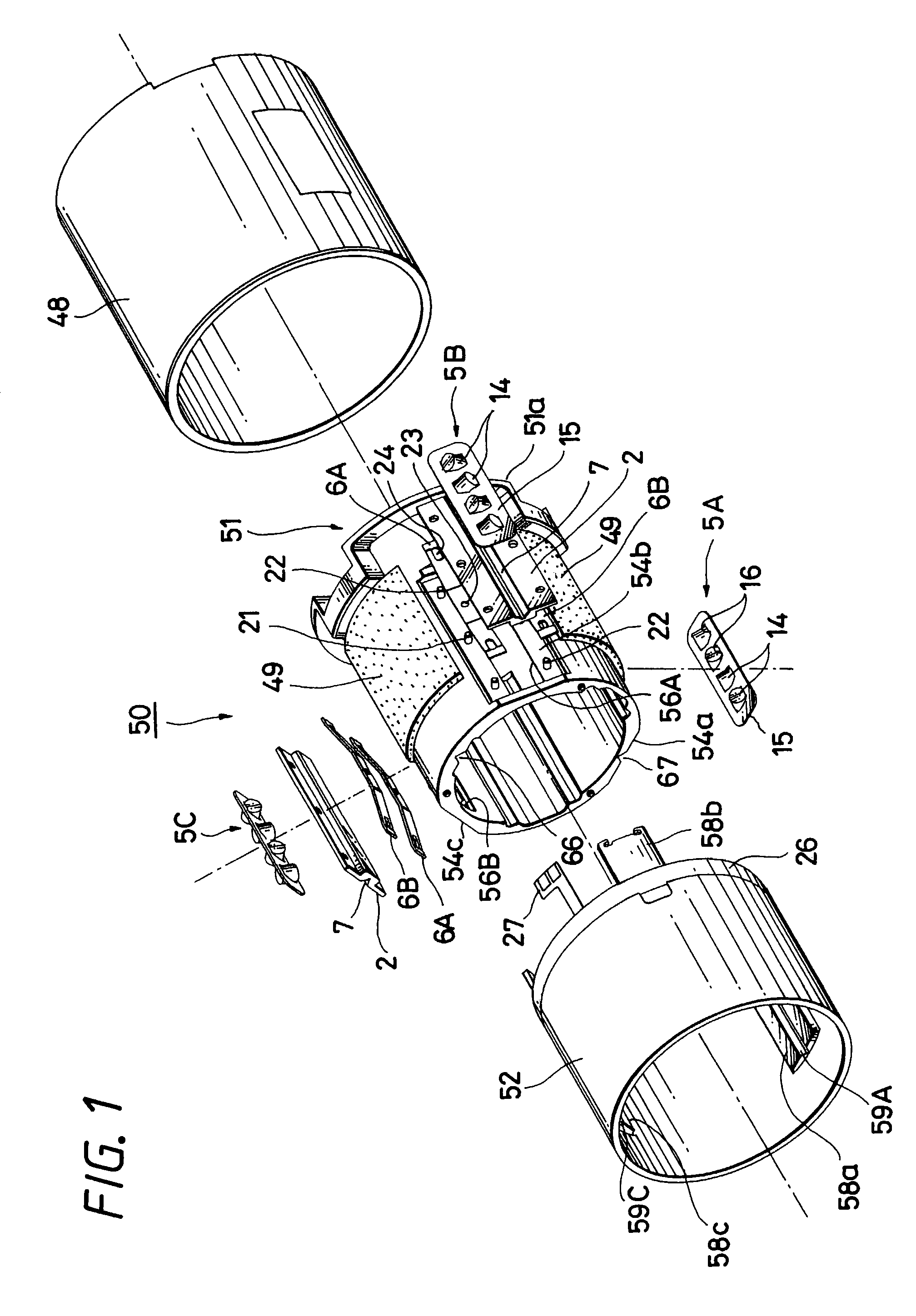
[0035]First, a linearly movable rolling guide apparatus for use with a lens apparatus according to the present invention will be described. FIG. 3 is an exploded perspective view showing a linearly movable rolling guide apparatus according to the present invention. As shown in FIG. 3, a linearly movable rolling guide apparatus, generally depicted by reference numeral 1, is composed of a guide member 2 including a first guide groove 7, a movable member 3 including a second guide groove 8, a fixed member 4 for holding the guide member 2, a rolling element unit 5 interposed between the first and second guide grooves 7 and 8 so as to become able to roll freely and a pair of leaf springs 6A and 6B which show an embodiment of a pre-load member.

[0036]The guide member 2 is formed of a plate-like member which is rectangular in plane shape and which has a T-like cross-section in the direction perpendicular to its longitudinal direction. The guide member 2 has at its substantially central port...

second embodiment

[0052]Specifically, as shown in FIG. 4, the linearly movable guide apparatus 31 is composed of the guide member 2 including the first guide groove 7, the movable member 3 including the second guide groove 8, the fixed member 4 for holding the guide member 2, the rolling element unit 5 provided between the first and second guide grooves 7 and 8 so as to roll freely and the two sets of the plate-like permanent magnets 32A and 32B which show the pre-load member.

[0053]Each of the plate-like permanent magnets 32A and 32B is composed of first and second magnet plates 33 and 34. The first magnet plate 33 and the second magnet plate 34 are identical to each other. Accordingly, in this embodiment, the two sets of the plate-like permanent magnets 32A and 32B are constructed by using the four identical magnet plates 33 and 34. Each of the magnet plates 33 and 34 is formed of a long size magnet of the size substantially the same as those of the bottom surface portions 19A and 19B of the fixed m...


PUM


Abstract

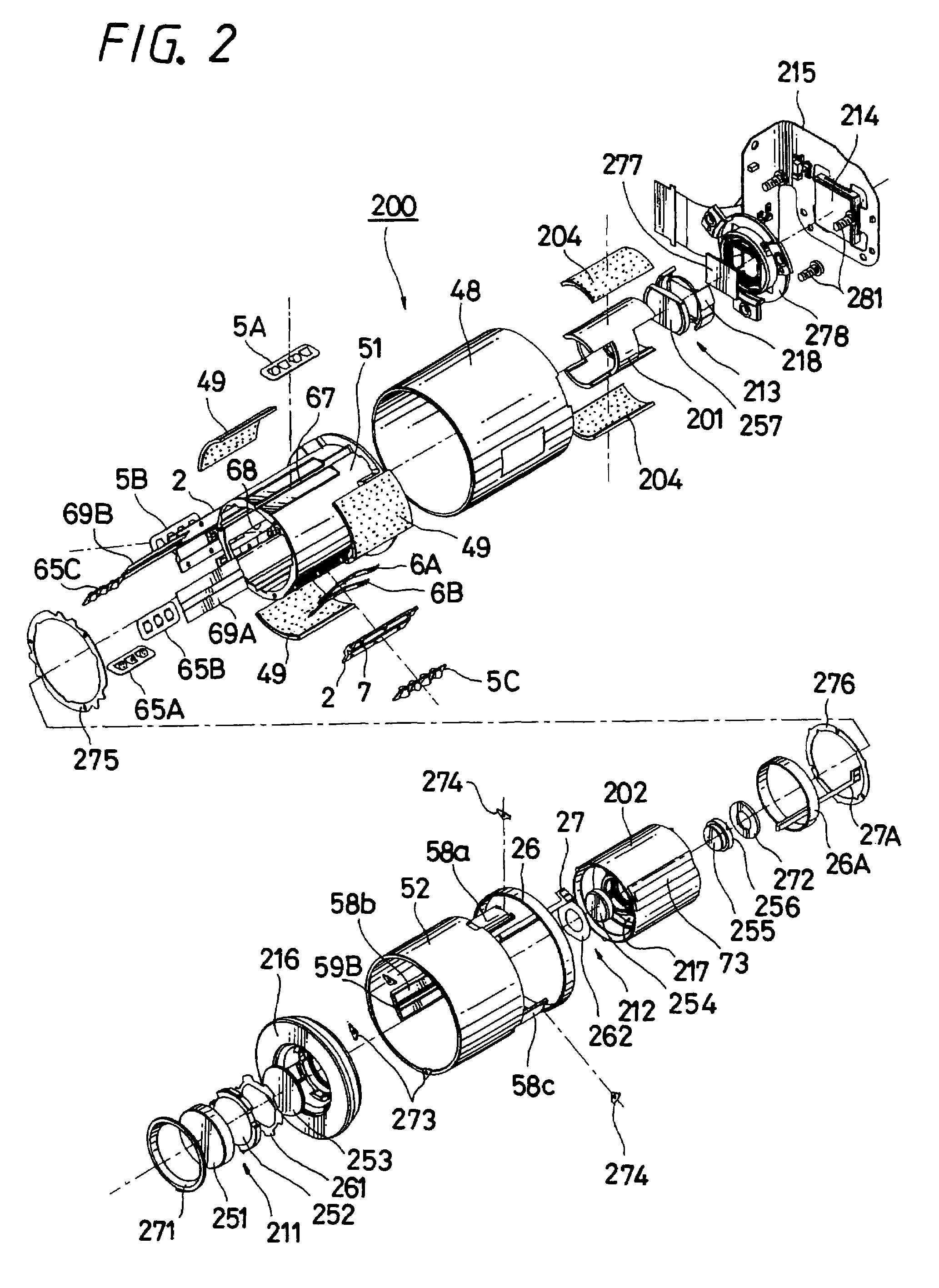
A lens apparatus and image pickup apparatus thereof. The lens apparatus includes a first fixed lens-barrel with fixed-side first guide grooves and fixed-side second guide grooves, a first movable lens-barrel arranged at the outside of the fixed lens-barrel, movable-side first guide grooves, a second movable lens-barrel arranged at the inside of the fixed lens barrel, and movable-side guide grooves. Three first rolling element units are provided between the fixed-side guide grooves and the movable-side first guide grooves, and three second rolling element units are provided between the fixed-side second guide grooves and the movable-side second guide grooves. The first movable lens-barrels and the second movable lens-barrels are supported to the one-group lens and the two-group lens in such a manner that they can be independently moved in the optical axis directions of the first and second lenses.

Description

TECHNICAL FIELD[0001]The present invention relates to a lens apparatus consisting of a fixed lens-barrel, first and second movable lens-barrels fitted into the inside and the outside of the fixed lens-barrel and more than two rolling element units provided between the first and second movable lens-barrels so that a plurality of movable lens-barrels can be moved straight and an image pickup apparatus including such a lens apparatus.BACKGROUND ART[0002]Cited Patent Reference 1, for example, has described an example of this kind of lens apparatus according to the related art. Specifically, the Cited Patent Reference 1 has described a linear actuator, an optical device and a lens-barrel for driving an image pickup lens in an image pickup apparatus such as a camera and a video camera. The lens-barrel described in this Cited Patent Reference 1 is characterized in that this lens-barrel uses a linear actuator in which a moving lens group movable in the optical axis direction, a lens holding...

Claims


Application Information

Patent Timeline
Patent Type & Authority Patents(United States)
IPC IPC(8): G02B7/02
CPCF16C29/041G02B7/10G02B7/102
Inventor MATSUMOTO, KENICHI
Owner SONY CORP
Learn More