Minesweeping device

a technology of magnetic signature and sweeping device, which is applied in the manufacture/treatment of superconductor devices, auxiliaries, offensive equipment, etc., can solve the problems of difficult if not impossible air sport of minesweeping system incorporating permanent magnets, limited source strength and orientation options, and heavy structure of heavy structure, etc., to facilitate the generation of desired magnetic signatures.

Inactive Publication Date: 2010-02-09
COMMONWEALTH OF AUSTRALIA
View PDF20 Cites 6 Cited by
  • Summary
  • Abstract
  • Description
  • Claims
  • Application Information

AI Technical Summary

Benefits of technology

[0014]Preferably, the control unit is arranged, in use, such that the magnetic output is variable as a function of time, orientation and / or position, for facilitating generating desired magnetic signatures for simulating vessels.
[0025]Preferably, the method further comprises varying the magnetic output, as a function of time and / or position, for facilitating generating desired magnetic signatures for simulating vessels.

Problems solved by technology

Current minesweeping systems incorporating permanent magnets have the disadvantage of being very heavy structures, and, in general, are difficult if not impossible to sport by air because of potential interference with navigational compasses.
Furthermore, they have limited options on source strength and orientation with respect to direction of advance of the minesweeping system.
Other current minesweeping systems incorporating conventional electromagnets tend to require power generators on board the tow platforms and tow cables which involve power down the cable, which then tend to result in fairly large cable structures.
As a result, substantial bollard pull capability is required on the tow platform, which limits the versatility of such minesweeping systems.

Method used


Image

  • Minesweeping device
  • Minesweeping device
  • Minesweeping device

Examples


Embodiment Construction

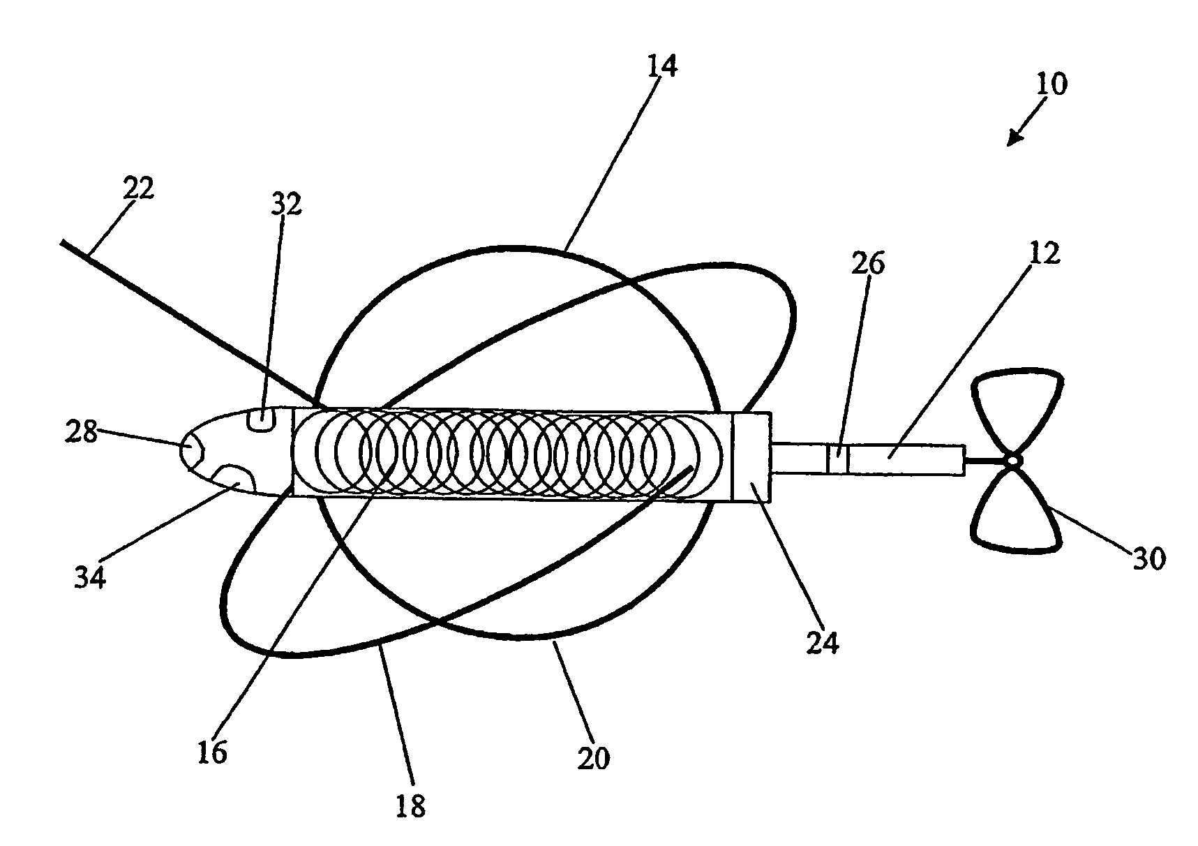
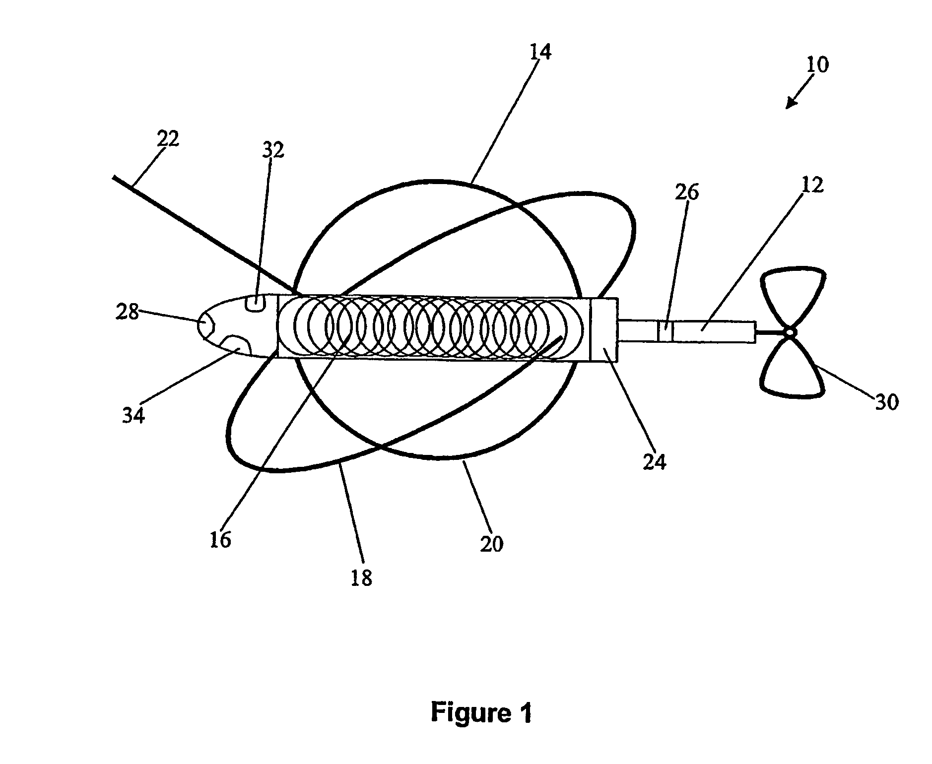
[0033]Referring first to FIG. 1, a minesweeping device 10 embodying the present invention integrates a water driven turbine generator 12 with a super conducting material magnet structure 14 in the one vessel. In the embodiment shown in FIG. 1, the superconducting material magnet structure 14 comprises a longitudinal magnet coil structure 16, as well as vertical and athwartship magnet coil structures 18 and 20 respectively. The coil structures are formed from a high Tc superconductor. Multi-Filamentary Composite wire BSCCO-2223 (Bi2Sr2Ca2Cu3O10+δ) or a Coated Conductor Composite manufactured by American Superconductor Corporation with YBCO (YBa2Cu3O7−δ), once commercially available, may be used.

[0034]The minesweeping device 10 is connected to a tow cable 22, which does not have to provide power down the cable capabilities due to the on-board power generation utilising the water driven turbine generator 12. It has been recognised by the applicant that superconducting material magnets ...


PUM


Abstract

A magnetic signature minesweeping device (10) comprising a water driven turbine power generator (12) and a superconducting material magnet (14), wherein the turbine power generator is arranged, in use, to supply a driving current for the superconducting material magnet (14) when the minesweeping device is towed through the water. In a further embodiment a control unit (24) is arranged, in use, to control the magnetic output of the superconducting magnet (14) and the power output of the turbine power generator (12). Further more a method of minesweeping using the device (10), and an array of the devices (10) is disclosed.

Description

CLAIM OF PRIORITY[0001]This application is a U.S. National Stage Filing under 35 U.S.C. 371 from International Patent Application No. PCT / AU2003 / 001678 filed on Dec. 17, 2003, and published in English as WO 2004 / 054873 A1 on Jul. 1, 2004, which claims priority under 35 U.S.C. §119(a)-(d) or 365(b) of Australian Application No. 20029543407 filed Dec. 18, 2002, which applications and publication are incorporated herein by reference.FIELD OF THE INVENTION[0002]The present invention relates broadly to a minesweeping device and to a method of minesweeping, in particular in respect of magnetic signature minesweeping.BACKGROUND OF THE INVENTION[0003]Magnetic signature minesweeping systems typically comprise permanent magnets, conventional electromagnets or conducting loops to generate magnetic fields for simulating magnetic signatures of water vessels. The purpose of magnetic signature minesweeping systems is to trigger underwater mines by simulating the magnetic signatures of vessels, whi...

Claims


Application Information

Patent Timeline
Patent Type & Authority Patents(United States)
IPC IPC(8): B63G7/06B63J3/04
CPCB63G7/06F41H11/28B63G2007/065B63J3/04Y02T90/38Y02T70/70B63J2003/046Y02T70/00Y02T90/40
Inventor THEOBALD, ALANWHITE, KENNETH GEORGE
Owner COMMONWEALTH OF AUSTRALIA
Why Eureka
Try Eureka