Combination descender, pulley and force limiting rope brake

a technology of rope brake and pulley, which is applied in the direction of sport apparatus, portable lifting, application, etc., can solve the problems of not being able to perform the combined functions of prior art devices of which the applicant is aware, and the device is not rated for rescue-sized loads, etc., and achieves the effect of easy release or removal

a technology of rope brake and pulley, which is applied in the direction of sport apparatus, portable lifting, application, etc., can solve the problems of not being able to perform the combined functions of prior art devices of which the applicant is aware, and the device is not rated for rescue-sized loads, etc., and achieves the effect of easy release or removal

US7658264B2Active Publication Date: 2010-02-09MAUTHNER KIRK MARTIN

Image

  • Combination descender, pulley and force limiting rope brake
  • Combination descender, pulley and force limiting rope brake
  • Combination descender, pulley and force limiting rope brake

Examples


Embodiment Construction

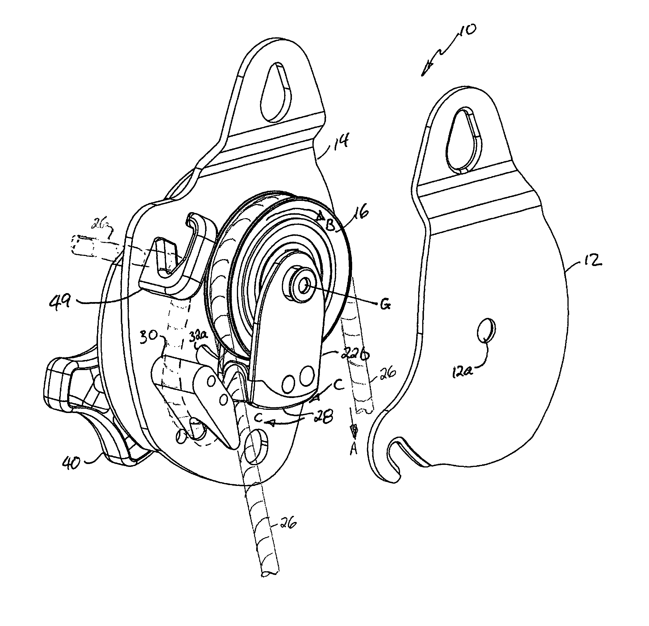
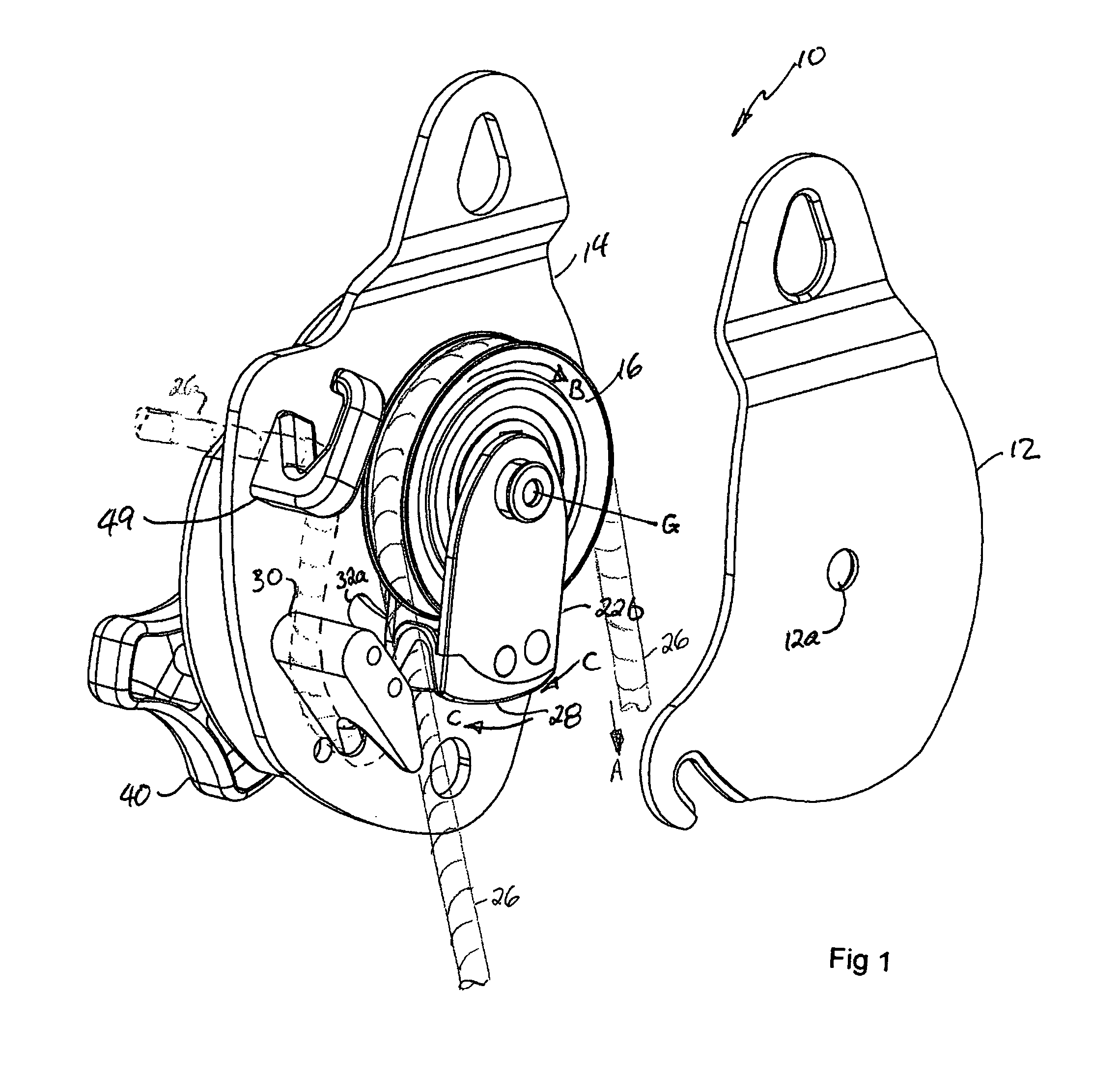
[0025]The device of the present invention combines the capabilities of, firstly, a variable friction descent control device usable for either lowering rescue-sized loads or rappelling, with, secondly, a ratchet-function pulley, and, thirdly, a force limiting rope brake suitable for belaying rescue-sized loads. The device is adapted to accept a range of rescue rope diameters, is relatively lightweight, and is intended both to reduce the complexity associated with changeovers from lowering to raising and to minimize specialization of equipment between mainline and belay lines. The device in one embodiment may be loaded onto a length of rope anywhere along the length of the rope, rather than merely from the end of the rope as in the prior art.

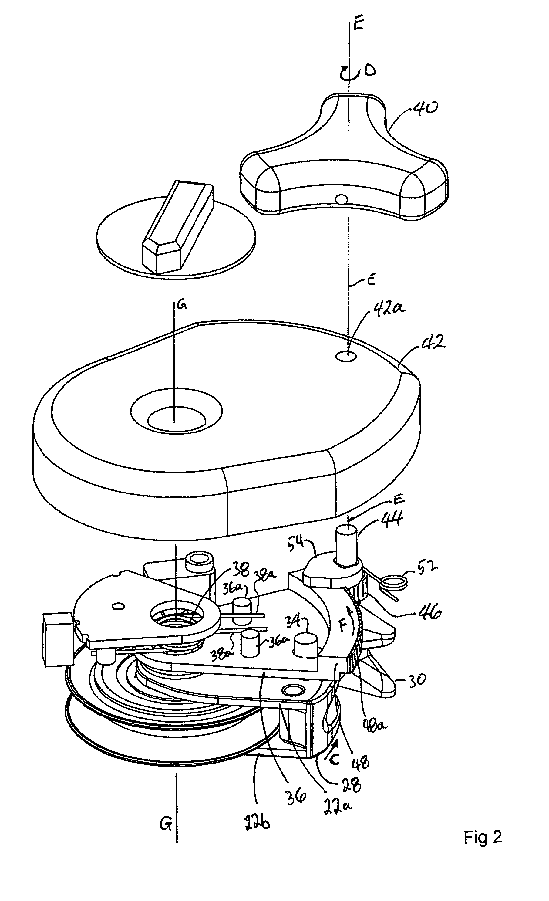
[0026]As seen in the accompanying Figures wherein corresponding reference numerals denote corresponding parts in each view, within device 10 generally parallel front and back plates 12 and 14 respectively provide a primary framework supporting, an...


PUM


Abstract

A combination descender, pulley, and force limiting rope brake for rope rescue has a supporting plate having a one-way pulley sheave rotatably mounted thereto for free-wheeling rotation of the sheave in only a first rotational direction. A fixed brake member is mounted rigidly to the supporting plate. A movable brake member is pivotally mounted to the supporting plate. A pinching opening is defined by the gap. The rope passes in a first direction through the gap when the sheave is free-wheeling in the first rotational direction. The movable brake member translates relative to the fixed brake member in cooperation with rotation of the sheave. Rotation-under-load of the sheave in an opposite rotational direction urges translation of the movable brake member towards the fixed brake member from an open position, wherein the pinching opening is open sufficiently to allow the rope to freely pass therethrough, to a closed position wherein the movable brake member closes the pinching opening so as to frictionally pinch the rope at a preset minimum opening of the pinching opening.

Description

CROSS REFERENCE TO RELATED APPLICATION[0001]This application claims priority from U.S. Provisional Patent Application No. 60 / 661,900 filed Mar. 16, 2005 entitled Combination Descender, Pulley and Force Limiting Rope Brake.BACKGROUND OF THE INVENTION[0002]Rope rescue is essentially an access and transportation issue of moving a subject or patient from a place of predicament to a place of care. Ropes are used to raise, lower, and even horizontally move a patient and / or rescue attendant. This is accomplished with the use of variable-friction descent control devices, mechanical advantage systems such as pulley systems, rope grabs, brake or hitch devices, and back-up devices such as force limiting rope brakes. However, no prior art device of which Applicant is aware can perform the combined functions of variable friction descent control, efficient pulley with a built-in ratchet, and a belay device capable of handling rescue-sized loads, in one simple device.[0003]Conventionally, to conve...

Claims


Application Information

Patent Timeline
09 Feb 2010
Publication
US7658264B2
IPC
A62B1/20
CPC
A62B1/14; B66D3/046; B66D3/10
Inventors
MAUTHNER, KIRK MARTIN