Filter element and filter system for the intake air of an internal combustion engine

a filter element and filter system technology, applied in the field of filter elements, can solve problems such as oscillation damage to the filter element, and achieve the effect of avoiding damage to the internal combustion engin

Active Publication Date: 2010-02-09
MANN HUMMEL GMBH
View PDF27 Cites 58 Cited by
  • Summary
  • Abstract
  • Description
  • Claims
  • Application Information

AI Technical Summary

Benefits of technology

[0004]Another object of the invention is to provide a filter element and filter system in which a seal can be easily and cost-effectively attached to a filter body.
[0021]In one advantageous embodiment, the geometry of the housing section communicating with the hard component includes elevations and / or indentations. The hard component also has elevations and / or indentations, such that the elevations of the housing section engage the indentations in the hard component, and the elevations of the hard component engage the indentations in the housing section. The geometries correspond in such a way that they prevent insertion of a wrong filter element or incorrect insertion of a correct filter element. The inability of the filter element to assume its proper position within the housing prevents the housing from being closed, and in that way, the selection of an improper filter element or mis-positioning of a filter element can be detected. This prevents the filter system from being operated with the wrong or with an incorrectly installed filter element and avoids damage to the internal combustion engine. The housing can be closed only if an appropriate filter element is inserted in the specified orientation, so that improperly filtered air cannot damage the internal combustion engine.

Problems solved by technology

Since the seal is formed of an elastic material, the filter element can oscillate or vibrate axially inside the parts of the housing, which oscillation damages the filter element.

Method used


Image

  • Filter element and filter system for the intake air of an internal combustion engine
  • Filter element and filter system for the intake air of an internal combustion engine
  • Filter element and filter system for the intake air of an internal combustion engine

Examples


Embodiment Construction

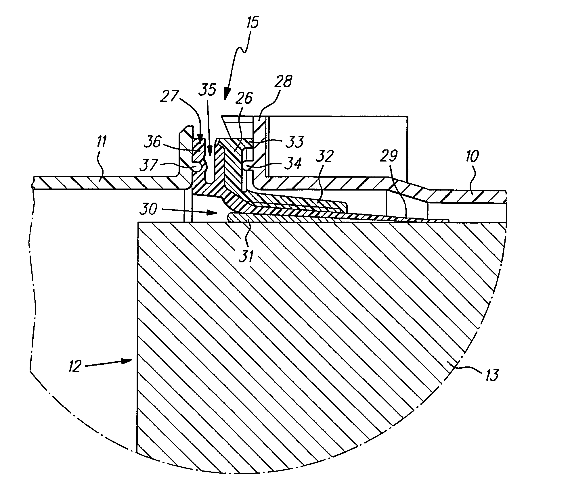
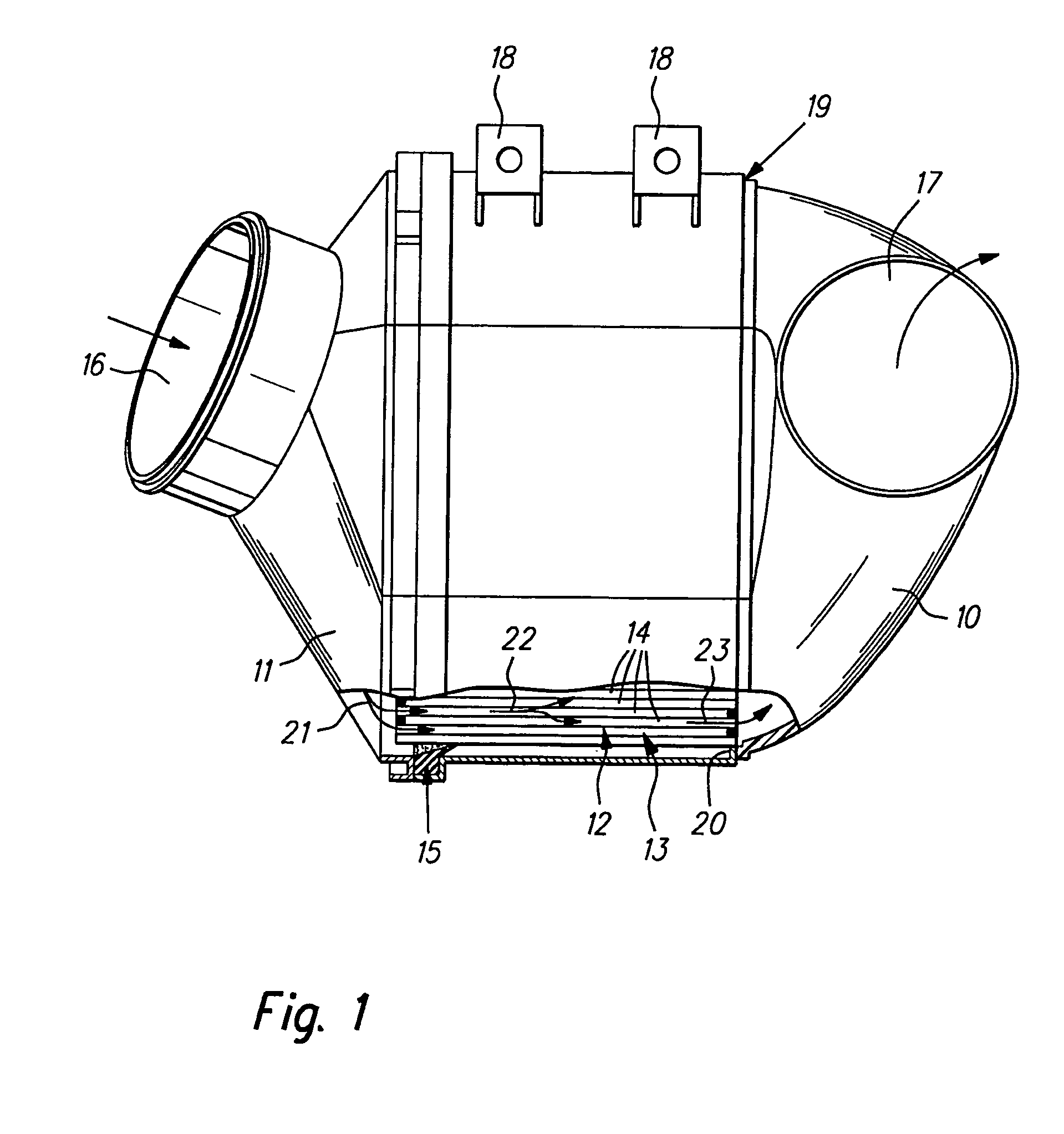
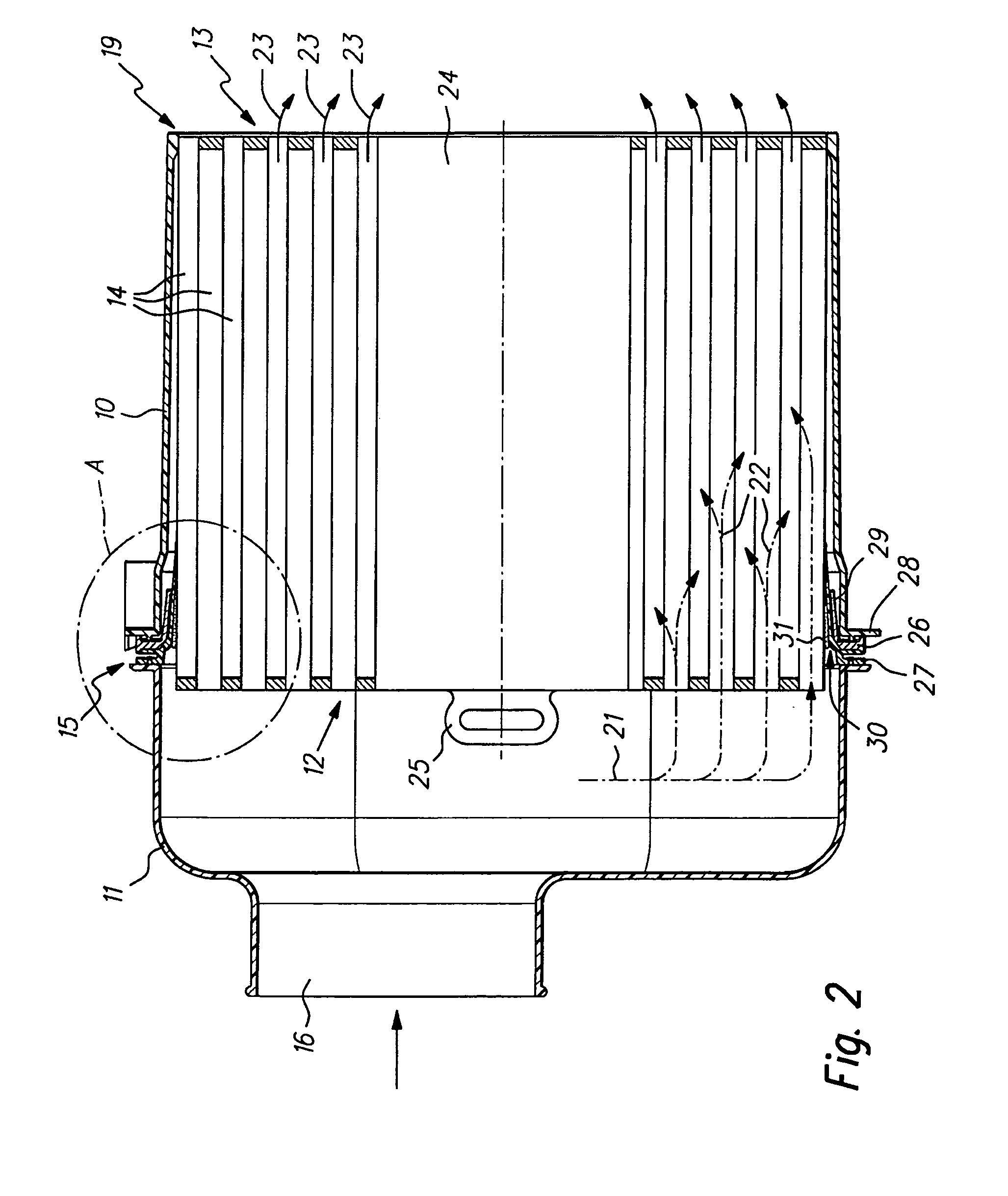
[0032]FIG. 1 is a general view of a filter system which is partially cutaway in the lower portion of the figure. The filter system has a housing 10 with a lid 11 and an oval filter insert 12. The lid 11 is configured in such a way that it closes the housing 10, so that the housing 10 and the lid 11 form a filter enclosure. The filter insert 12 comprises a filter coil 13 with alternately closed channels 14 and a seal 15. The seal 15 is disposed between the lid 11 and the housing 10. The construction and arrangement of the seal 15 will be described in greater detail with reference to the subsequent figures.

[0033]The lid 11 has an inlet 16 through which the air to be filtered flows into the filter housing. The outlet 17 for the filtered air is arranged in the housing 10. The filter insert 12 is arranged in the filter housing such that the inlet 16 is separated from and sealed relative to the outlet 17. The filter insert 12 extends axially into the housing 10. The housing 10, which in t...


PUM

PropertyMeasurementUnit
sealing areaaaaaaaaaaa
vibration dampingaaaaaaaaaa
elevationsaaaaaaaaaa

Abstract

A filter element (12), particularly for the intake air of an internal combustion engine. The filter element (12) has a filter body (13) and a seal (15) disposed circumferentially around the filter body (13). The seal (15) is bonded to the filter body (13) with an adhesive (31) and includes a hard component (26) and a soft component (27). The hard component (26), which rests directly on a housing section, prevents the filter element (12) from moving relative to this housing section, and since the filter element cannot move relative to the housing section, damage to the filter element is avoided.

Description

BACKGROUND OF THE INVENTION[0001]The present invention relates to a filter element, particularly for the intake air of an internal combustion engine or a compressor, comprising a filter body and a seal circumferentially disposed around the filter body. The invention further relates to a filter system incorporating such a filter element.[0002]Published international patent application no. WO 2004 / 020075 discloses a filter system for the intake air of an internal combustion engine in which a filter element is clamped between two parts of the housing. The filter element is a wound filter formed of a coiled filter medium and a profiled seal disposed along the circumference. The profiled seal is formed of an elastic band circumferentially bonded to the filter medium coil. To this end, the seal has a circumferential surface extending parallel to the outside circumference of the filter coil and is adhesively bonded to the coiled filter medium. To obtain a good bond between the seal and the...

Claims


Application Information

Patent Timeline
Patent Type & Authority Patents(United States)
IPC IPC(8): B01D46/00
CPCB01D46/0005B01D46/525F02M35/024B01D2271/025B01D2271/027
Inventor KOPEC, EDVARDRUHLAND, KLAUS-DIETERSTEINS, OLIVERPOH, RALF
Owner MANN HUMMEL GMBH
Why Eureka
Try Eureka