Magnetic field generating device
Inactive Publication Date: 2010-02-16
NAU JEFFREY J
16 Cites 13 Cited by
AI-Extracted Technical Summary
Problems solved by technology
However, owing to the limitations imposed by Earnshaw's Theorem, the magnetic bearing...
Abstract
A magnetic field generator that utilizes two concentric rings with similarly charged electro-magnets to repel the rings in opposite orbits around an electrically charged central core to create the magnetic field.
Application Domain
Dynamo-electric brakes/clutchesSliding/levitation railway systems +2
Technology Topic
Concentric ringNuclear magnetic resonance +4
Image
Examples
- Experimental program(1)
Example
[0039]With regard to the reference numerals used, the following numbering is used throughout the various drawing figures.
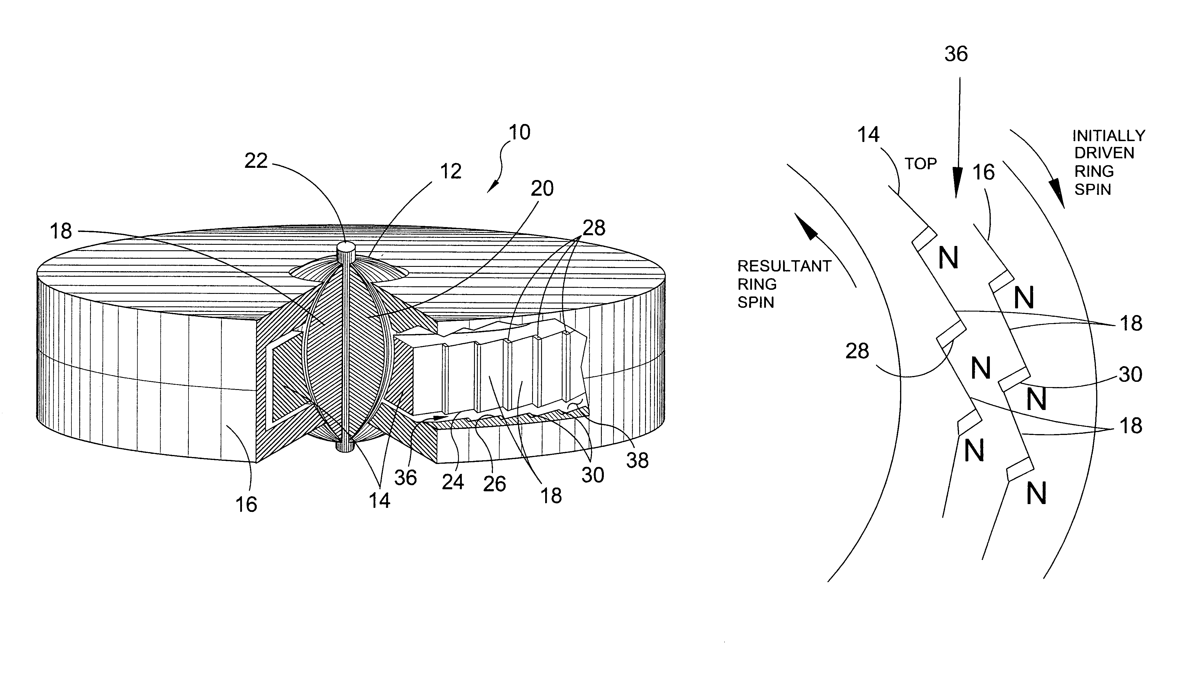
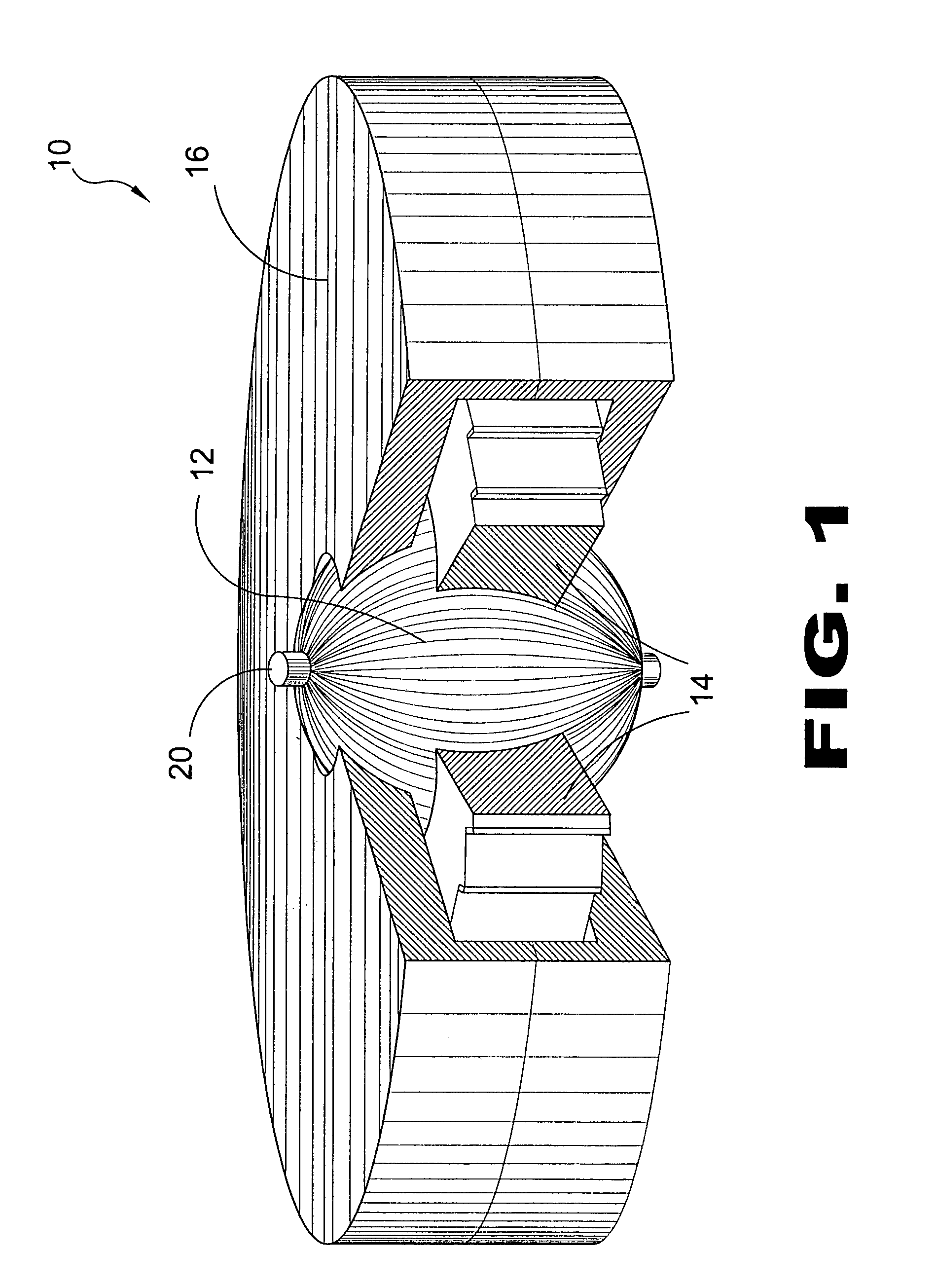
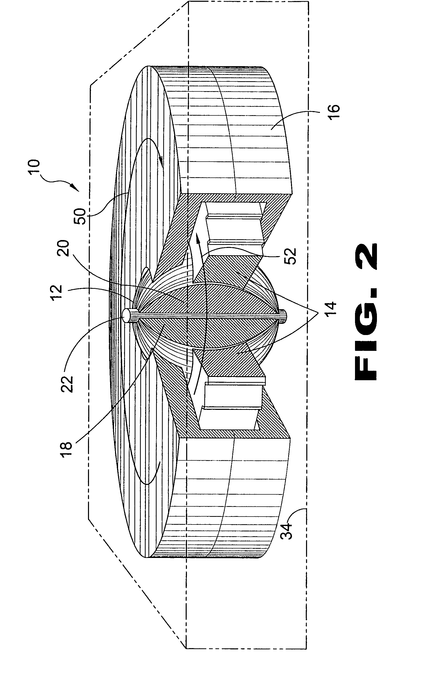
[0040] 10 Gravity-Opposing Repulsion Generator 12 central sphere 14 inner ring 16 outer ring 18 dielectric material 20 conductive material 22 conductive mounting rod 24 outer face of 14 26 inner face of 16 28 north magnet of 14 30 north magnet of 16 32 starter motor 34 housing 36 inner ring drive 38 interface area 40 lower half of 16 42 upper half of 16 44 outer ring bolt 46 bearings 48 dielectric support 50 rotation of 16 52 rotation of 14 54 mechanical gear mesh 56 electrical contact brush 58 thermal control means 60 capillary tubing
DETAILED DESCRIPTION OF THE PREFERRED EMBODIMENTS
[0041]In order that the invention may be more fully understood, it will now be described, by way of example, with reference to the accompanying drawing in which:
[0042]FIG. 1 is a cut-away perspective view of the present invention 10 having a solid conductive sphere 12. The present invention 10 is an anti-gravitational generator comprising a central sphere 12 surrounded by an inner ring 14 within an outer ring 16, rotating about a vertical axis. A spherical core 12 is comprised of a core of conductive material and dielectric material insulated from outer engine casing, the outer surface is conductive/dielectric lines running vertically from pole to pole. Around the core 12 is an inner ring 14 that spins in one direction, looking from the top, counterclockwise, it is charged in one direction through brushes. An outer ring 16 placed around the inner ring 14 will spin in the opposite direction, clockwise and will be charged with an opposite flow of electricity through the brushes. Bearings and dielectric insulation are used to maintain electrical separation of inner and outer rings. The interface area is what drives the inner ring 14.
[0043]FIG. 2 is a cut-away perspective view of the present invention 10 having a spherical core 12 of conductive metal 20 with interdisposed dielectric material 18. The present invention 10 is a gravity-opposing repulsion generator comprising a spherical core 12 surrounded by an inner ring 14 within an outer ring 16 rotating about a vertical axis. Shown are the clockwise rotation 50 of the outer ring 16 and the counter-clockwise rotation 52 of the inner ring 14. The core 12 is charged through the conductive mounting rod 22. the entire unit is enclosed within a housing 34 as depicted in phantom line.
[0044]FIG. 3 is a sectional perspective view of the present invention 10 with a portion of the outer ring 16 cut-away. The charged opposing northern magnetic fields of the inner ring face 26 and the outer ring face 24 provide thrust to rotate the two rings in opposite directions. The inner ring drive 36 includes the inner ring face magnets 28, the outer ring face magnets 30 and the interface area 38 defined by the gap between the two ring faces 24,26 to drive the inner ring. The inner ring 14 is driven when the opposing magnetic fields interact with one another in the interface area 38. The rings 14,16 will drive faster as electrical input is evenly increased thereto resulting in a repulsive magnetic field that forms when the core is charged.
[0045]FIG. 4 is a side view of the core 12 surface of the present invention. Shown are the interspersed sections of dielectric material 18 and conductive material 20. During the basic start up procedure the starter motor is energized causing the outer ring 16 to start rotation, both the inner ring 14 and the outer ring 16 are then charged (oppositely) through brushes causing the inner ring 14 to begin rotation in the opposite direction via the interface; voltage increase causes ring acceleration, which creates an anti-gravity field, further voltage increase causes stronger repulsion then charging the core magnifies the repulsion. To induce magnetic field, the core 12 face lines are vertical and the ring face lines are diagonal correspondingly to direction of ring rotation.
[0046]FIG. 5 is a top view of the core 12 face of the present invention. The face lines are formed by the alternating sections of conductive material 20 and dielectric material 18. To induce magnetic field, the core 12 face lines are vertical and the ring face lines are diagonal correspondingly to direction of ring rotation.
[0047]FIG. 6 is a side view of an alternate core 12 face of the present invention. An alternate configuration for inducing flow is to have the core 12 face lines diagonally in correspondence with ring direction and face lines on the inner ring 14 and the outer ring 16 being vertical thereby accomplishing the same result as the preferred configuration shown in FIG. 4.
[0048]FIG. 7 is a sectional side view of the assembly of the present invention 10. Shown is the core 12 with the concentrically disposed inner ring 14 and outer ring 16 and the relationship of the opposing magnets 28,30 of the interface area 38 located therebetween thereby defining the inner ring drive 36.
[0049]FIG. 8 is a sectional side view of the assembly of the present invention 10. Shown is one possible set-up of bearing 46 and support 48 configuration in order to maintain inner ring 14 and outer ring 16 dielectric separation and stability. The inner ring 14 is supported and insulated by bearings 46 and dielectric supports 48. The outer ring 16 has an upper half 42 and a lower half 40 secured to another by bolts 44. The final assembly is mounted with more bearings 46 and supports 48 in a housing 34 mounted to the airframe.
[0050]FIG. 9 is general side view of the present invention 10. Shown is a preferred method of delivering electrical flow (as illustrated by the arrows) to the inner ring 14 and the outer ring 16 while maintaining dielectric separation through the usage of a basic brush 56 system and insulation elements. Also shown is basic top view of the inner ring drive 36. A starter motor 32 is provided to initiate the rotation of the outer ring 16 during start-up. A mechanical gear mesh 54 is shown as a means for communicating with the outer ring 16 through the housing 34.
[0051]FIG. 10 is a partial side view of an alternate assembly of the present invention. Shown is an alternate brush 56 configuration and a means for providing thermal control 58 by coolant path flow through capillary tubes 60 manufactured in various components as illustrated by items 1-5. Thermal control is critical due to the high amperage levels required for operation. Any suitable brush 56 configuration may be used that achieves the objective of supplying electricity to the inner and outer ring while maintaining dielectric separation.
[0052]FIG. 11 is an illustrated view of the induced magnetic field 62 provided by the present invention. As electrical input is evenly increased, the rings 14,16 will drive faster to a point where a resultant magnetic field 62 forms by charging the core 12, the magnetic field should increase.
[0053]FIG. 12 is a top view of the inner ring drive area 36 of the present invention. When the outer ring is initially driven and then powered the inner ring is then powered resulting in inner ring drive by electromagnetic north-to-north repulsion.
[0054]FIG. 13 is a top view of the inner ring drive 36 of the present invention with the upper 42 and lower 40 halves of said outer ring configured so the ring faces are staggered. Staggering and addition of north-to-north magnetic faces may be employed to improve power of repulsive drive. Shown are the north-to-north magnetic faces of the upper halves of the inner ring and the outer ring offset from the lower halves of the inner ring and the outer ring to provide greater repulsion properties during operation.
[0055]It will be understood that each of the elements described above, or two or more together may also find a useful application in other types of methods differing from the type described above.
[0056]While certain novel features of this invention have been shown and described and are pointed out in the annexed claims, it is not intended to be limited to the details above, since it will be understood that various omissions, modifications, substitutions and changes in the forms and details of the device illustrated and in its operation can be made by those skilled in the art without departing in any way from the spirit of the present invention.
[0057]Without further analysis, the foregoing will so fully reveal the gist of the present invention that others can, by applying current knowledge, readily adapt it for various applications without omitting features that, from the standpoint of prior art, fairly constitute essential characteristics of the generic or specific aspects of this invention.
PUM


Description & Claims & Application Information
We can also present the details of the Description, Claims and Application information to help users get a comprehensive understanding of the technical details of the patent, such as background art, summary of invention, brief description of drawings, description of embodiments, and other original content. On the other hand, users can also determine the specific scope of protection of the technology through the list of claims; as well as understand the changes in the life cycle of the technology with the presentation of the patent timeline. Login to view more.