Welding electrode with contoured face

a welding electrode and contoured face technology, applied in the direction of electrode maintenance, soldering apparatus, manufacturing tools, etc., can solve the problems of difficult welding, difficulty in welding, and the tip or welding face of the electrode may be altered, so as to improve mechanical stability, facilitate welding, and good alignment

Active Publication Date: 2008-04-03
GM GLOBAL TECH OPERATIONS LLC
View PDF16 Cites 108 Cited by
  • Summary
  • Abstract
  • Description
  • Claims
  • Application Information

AI Technical Summary

Benefits of technology

[0010]The concentric ridges or grooves are formed, respectively, to have circular surfaces projecting outwardly from the face of the electrode or inwardly into the face of the electrode so that these formed surfaces engage and possibly penetrate the surface layer or film of a workpiece. Each (or some) of the concentric ridges or grooves may be separated from their radially-spaced neighbors by a flat ring-shaped surface in the face of the electrode. By way of example, the circular ridges or grooves are suitably formed to have a peak-to-base height in the range of about 20 μm to 200 μm with a peak-to-peak or base-to-base spacing (depending on the profile of the ridges or grooves) of 80 μm to 1500 μm. This circularly contoured welding face pattern is easily formed on new electrodes.
[0011]Thus, a single-step process is provided that simultaneously provides the benefits of both electrode dressing, i.e., electrode reshaping, good alignment, electrode surface cleanliness, etc., with the benefits of a texturing process, i.e., im

Problems solved by technology

Similar welding challenges arise in the welding of other light metal workpieces such as parts made of magnesium alloys.
The high electrical and thermal conductivity in combination with the insulating nature of the naturally-formed surface oxide of aluminum alloys (or magnesium alloys) makes them difficult to weld using spot welding

Method used


Image

  • Welding electrode with contoured face
  • Welding electrode with contoured face

Examples


Embodiment Construction

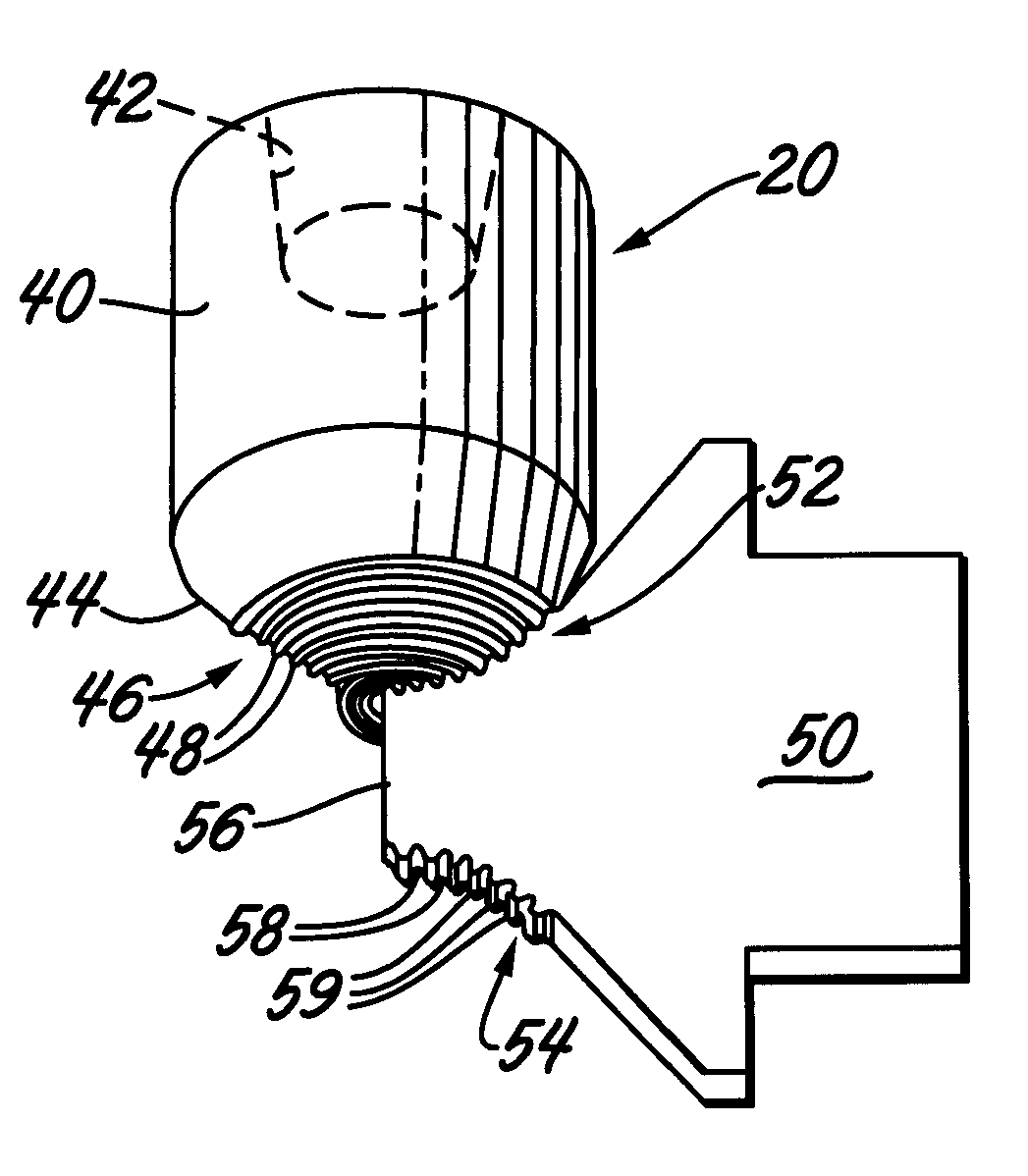
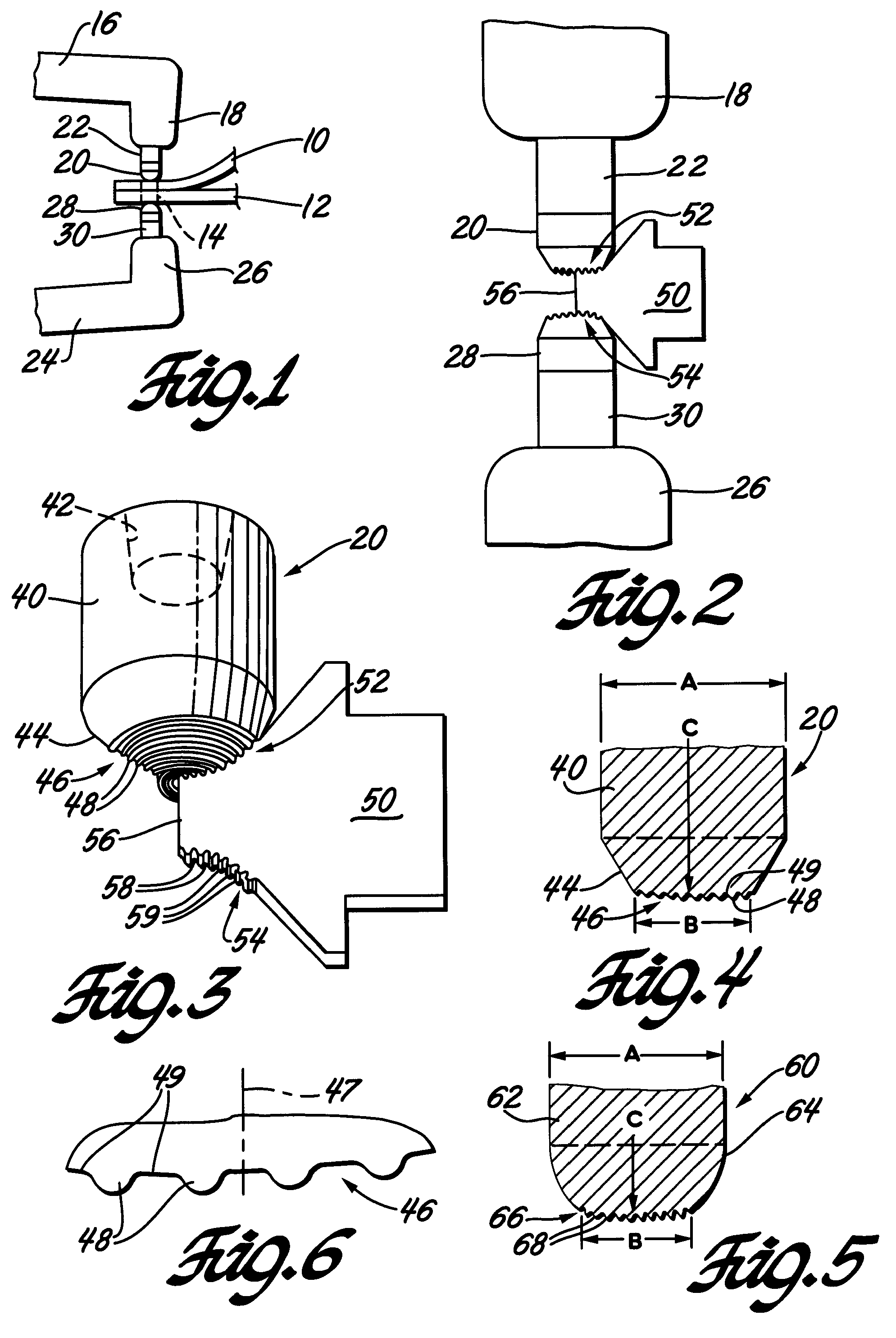
[0020]A welding electrode cap (or welding face) design is provided that is useful for forming spot welds in metal workpieces. The welding electrode cap is useful in spot welding operations generally, and it offers advantages for welding light metal workpieces such as aluminum alloy and magnesium alloy sheet materials. These materials often have an oxide film on surfaces contacted by the aligned and opposing electrodes and it is preferred that the electrode faces be shaped to engage and pierce the oxide film during welding.

[0021]In the manufacture of car doors, deck lids, liftgates, and the like, for example, it is often the practice to form these parts of complementary inner and outer sheet metal panels. The panels are of complex curvature for overall design effect and to contain any necessary electrical wiring and / or hardware between them. The formed panels usually have flanges at their peripheral edges for joining. An inner panel is placed against an outer panel and the assembled ...


PUM

PropertyMeasurementUnit
Lengthaaaaaaaaaa
Lengthaaaaaaaaaa
Lengthaaaaaaaaaa

Abstract

Welding electrodes with a welding face for contact with a metal surface for electrical resistance welding are provided with concentric contoured rings formed into the face. The rings may, for example, be ridges upstanding in the face or grooves depressed into the face. The contoured rings may be radially spaced with relatively flat (depending on the curvature of the face) intervening rings. When the electrode is pressed into contact with the surface of the workpiece for delivery of a welding current, the features of the concentric rings penetrate surface oxides or other conductivity barriers. When ongoing welding operations have eroded the contoured rings they may be rapidly reformed in the weld face in a surface re-dressing operation.

Description

TECHNICAL FIELD[0001]This invention pertains to welding electrodes for electrical resistance welding. More specifically this invention pertains to the formation of concentric geometric features on the welding face of the electrode for improved electrical contact with the workpiece.BACKGROUND OF THE INVENTION[0002]Current automotive vehicle manufacturing operations include, for example, the joining of two sheet metal layers by spot welding. Vehicle body panels such as doors, hoods, deck lids and liftgates are often assembled by joining inner and outer panels stamped from sheet metal of suitable metal alloys. Ferrous or aluminum alloys are often used. The thickness of each sheet metal layer may vary from less than one millimeter to more than four millimeters. Electrical resistance spot welding is often used to join such inner and outer panels or other metal parts.[0003]In the case of sheet metal body components, flats or flanges of two or three components are placed together and then ...

Claims


Application Information

Patent Timeline
IPC IPC(8): B23K11/30
CPCB23B5/166B23K11/3009Y10T82/16442B23K35/0205Y10T407/19B23K11/3063B23K11/14Y10T83/9372
Inventor SIGLER, DAVID R.KARAGOULIS, MICHAEL J.
Owner GM GLOBAL TECH OPERATIONS LLC
Why Eureka
Try Eureka