Corner-mounted battery fuse

Inactive Publication Date: 2010-02-16
YAZAKI NORTH AMERICA
View PDF46 Cites 59 Cited by
  • Summary
  • Abstract
  • Description
  • Claims
  • Application Information

AI Technical Summary

Benefits of technology

[0006]Accordingly, it is an object of this invention to provide a fuse device that uses the support of a battery housing to allow electrical cables with high torque requirements to be attached to the fuse device without damage to the fuse device or the electrical connection with the battery.
[0007]Another object of the invention is to strengthen the structure of the fuse device, without adding significant weight, by use of strategically placed ribs.
[0008]A further object of the invention is to make it easier to attach terminated cables to the fuse device by including an anti-rotation feature.
[0009]In carrying out this invention in the illustrative embodiment thereof, a fuse device has a top wall joined to two adjacent side walls. The top wall includes a battery terminal for securing the fuse device on a positive battery post of a battery in a housing or casing. The side walls each include protruding electrical connectors for mating with terminated electrical cables. Fuses o

Problems solved by technology

High twisting forces caused by torque generated when terminated electrical cables are attached to the fuse units or modules can damage the connection between th

Method used


Image

  • Corner-mounted battery fuse
  • Corner-mounted battery fuse
  • Corner-mounted battery fuse

Examples


Embodiment Construction

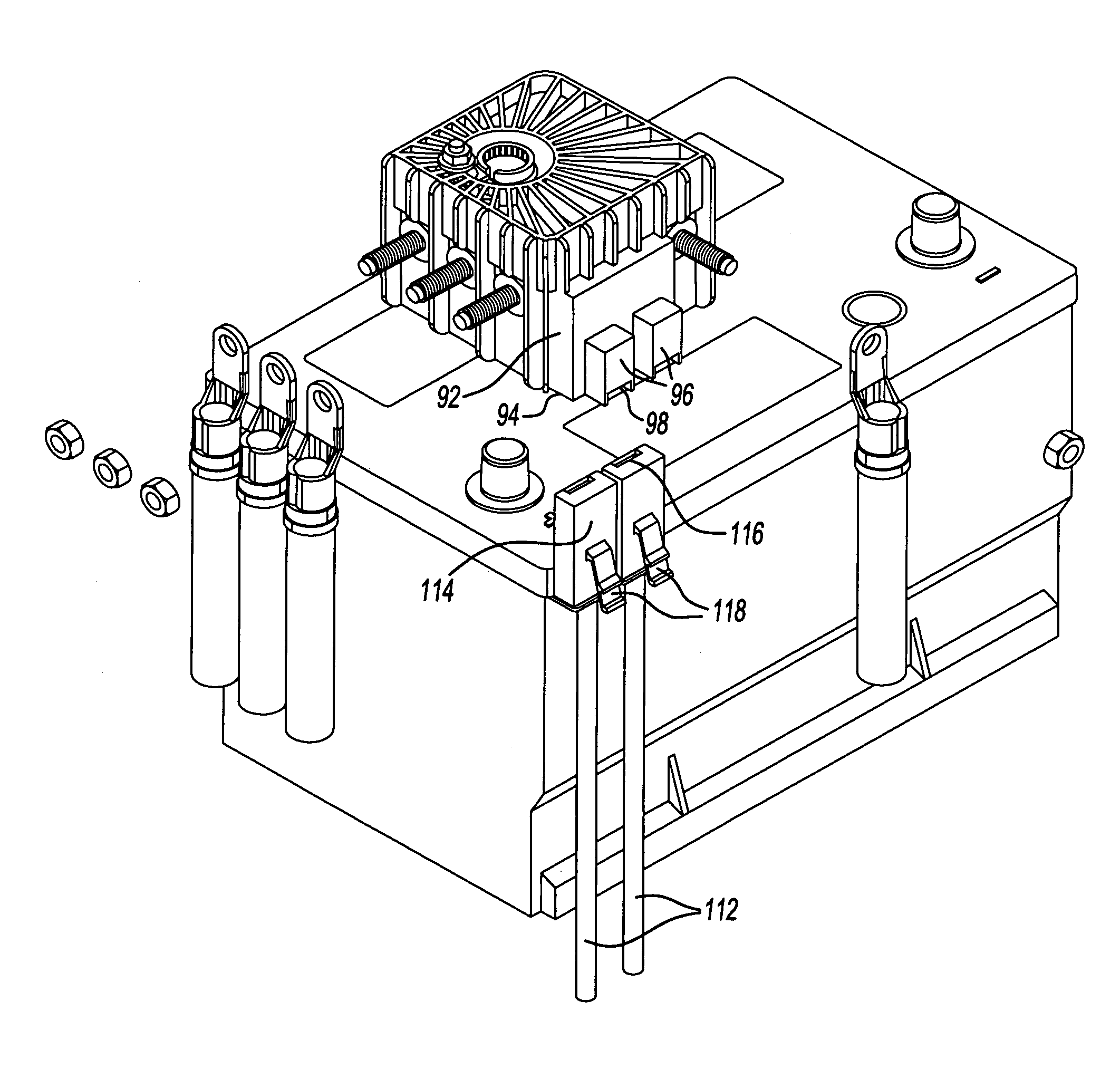
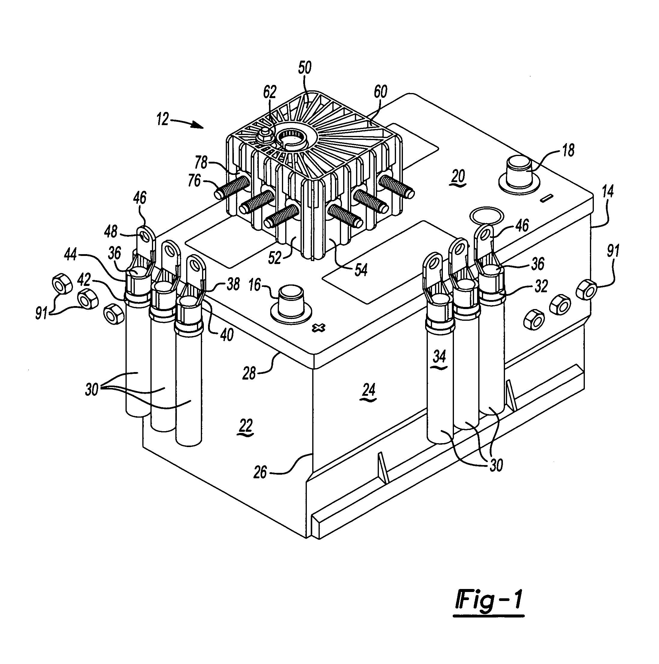
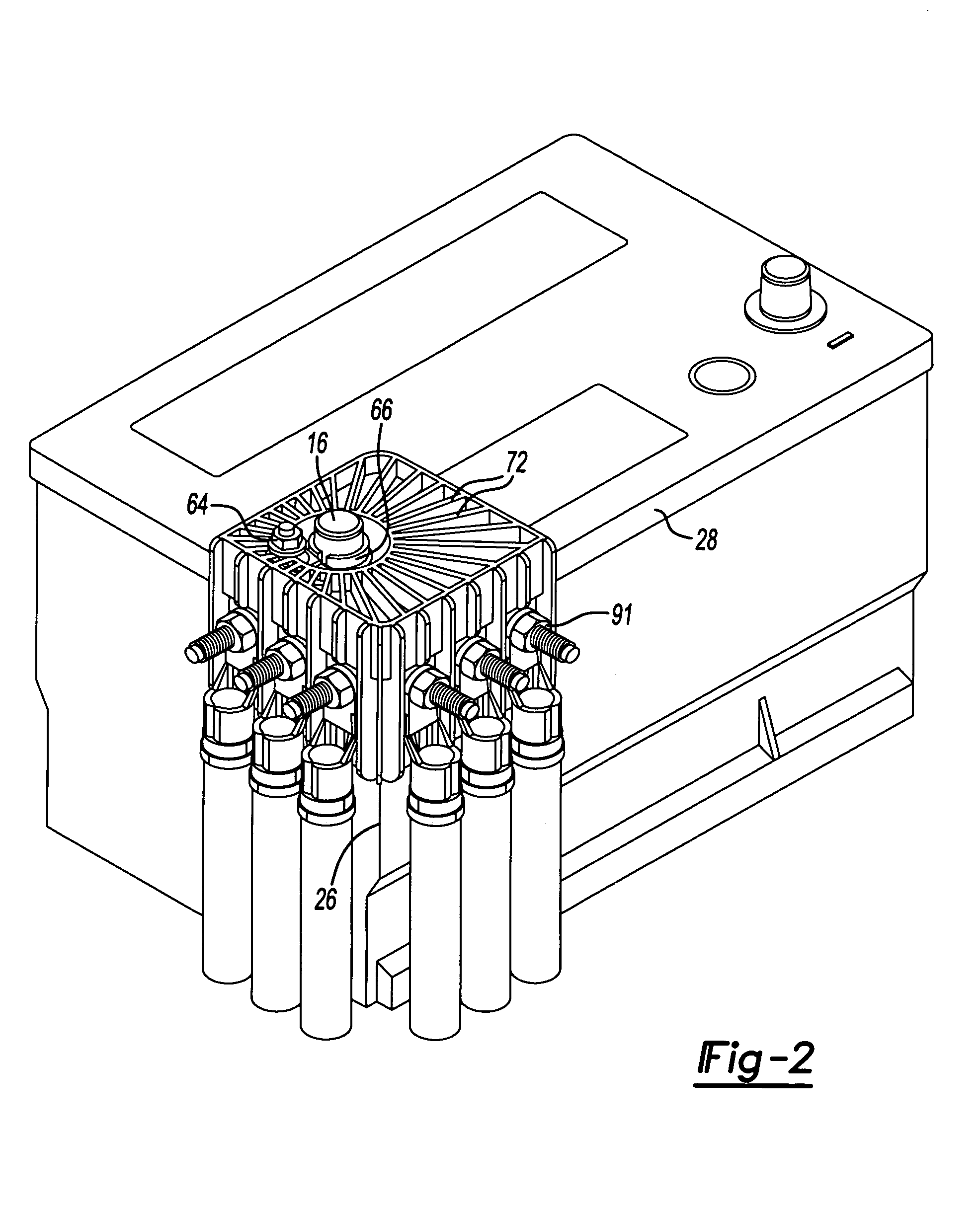
[0021]Referring now to FIG. 1, a fuse component or device 12 is illustrated in combination with a vehicle battery encased in a housing 14. The battery has a positive current battery post 16 and a negative current battery post 18. The housing 14 is generally rectangular with a first, planar top surface 20 from which the posts extend. A second planar surface 22 and a third planar surface 24 form adjoining side or side and front surfaces meeting at a corner 26. The second and third surfaces 22 and 24 are depicted as being at right angles to each other. The top surface 20 has a ledge 28 that slightly overhangs the side surfaces or side and front surfaces. The battery housing 14 is for illustrative purposes only and may have a different structure or design more closely associated with other power or voltage sources known in the art.

[0022]Electrical wires or cables 30 are broadly represented as being directed upward along the planar surfaces 22, 24 of the battery housing 14. The cables 30...


PUM


Abstract

A fuse device for fitting over and around a corner of a battery housing has a top wall and two side walls extending downward from the top wall. The side walls are joined at a corner. A battery terminal for mechanical and electrical attachment to a battery post is provided in the top wall. Electrical connectors for connection to terminals on the ends of electrical cables are mounted on the side walls of the fuse device. The electrical connectors are linked through the walls to the battery terminal by fuses. Ribs extending down the side walls from the top wall pass close by each electrical connector to strengthen the structure of the fuse device and prevent rotation of the terminals on the ends of the cables as they are secured to the fuse device. Recessed strengthening ribs in the top wall extend radially outward from the battery terminal.

Description

BACKGROUND OF THE INVENTION[0001]1. Field of the Invention[0002]This invention relates in general to fuses for vehicle battery connections and more specifically to a fuse device that mounts over and around a corner of a battery housing so the fuse device is stable during electrical cable attachment and vehicle operation.[0003]2. Discussion of Related Art[0004]Various mounting structures for use in distributing electrical current from an automotive battery through integral fuses to several circuits are known in the art. In U.S. Pat. No. 7,176,780, for example, a fuse unit hangs relatively free of the battery and relies mainly if not solely on the support of the battery post to which it attaches. In U.S. Pat. No. 5,645,448, the main fuse is located in a module mounted on a top surface of a battery. Only the terminals on the electrical cables can contact the battery side walls when a twisting force is applied to the module.[0005]High twisting forces caused by torque generated when term...

Claims


Application Information

Patent Timeline
IPC IPC(8): H01H85/46H01H85/165H01H85/20H01R13/46H05K7/00
CPCH01H85/044H01R11/287H01R13/68H01H2085/025H01H2085/0555
Inventor JETTON, JAMES THOMAS
Owner YAZAKI NORTH AMERICA
Why Eureka
Try Eureka