Video data correction circuit, control circuit of display device, and display device and electronic apparatus incorporating the same

a technology of video data and control circuit, which is applied in the field of display devices, can solve the problems of increasing the number of connection pins, increasing the number of rams, and difficulty in low power consumption, and achieves the effects of reducing the production cost of the display device, and reducing the number of pins

Inactive Publication Date: 2010-02-16
SEMICON ENERGY LAB CO LTD
View PDF44 Cites 5 Cited by
  • Summary
  • Abstract
  • Description
  • Claims
  • Application Information

AI Technical Summary

Benefits of technology

[0014]According to the conventional video data correction circuit having the aforementioned configuration, however, both the volatile memory and the nonvolatile memory incorporated in the circuit have large capacitance, leading to increased number of connection pins. In addition, the area occupied by the circuit increases with the increase in the number of bits, which prevents miniaturization and reduction in the production cost of a product. Further, low power consumption becomes difficult with the increase in the number of RAMs with large capacitance.

Problems solved by technology

According to the conventional video data correction circuit having the aforementioned configuration, however, both the volatile memory and the nonvolatile memory incorporated in the circuit have large capacitance, leading to increased number of connection pins.
Further, low power consumption becomes difficult with the increase in the number of RAMs with large capacitance.

Method used


Image

  • Video data correction circuit, control circuit of display device, and display device and electronic apparatus incorporating the same
  • Video data correction circuit, control circuit of display device, and display device and electronic apparatus incorporating the same
  • Video data correction circuit, control circuit of display device, and display device and electronic apparatus incorporating the same

Examples


embodiment mode 1

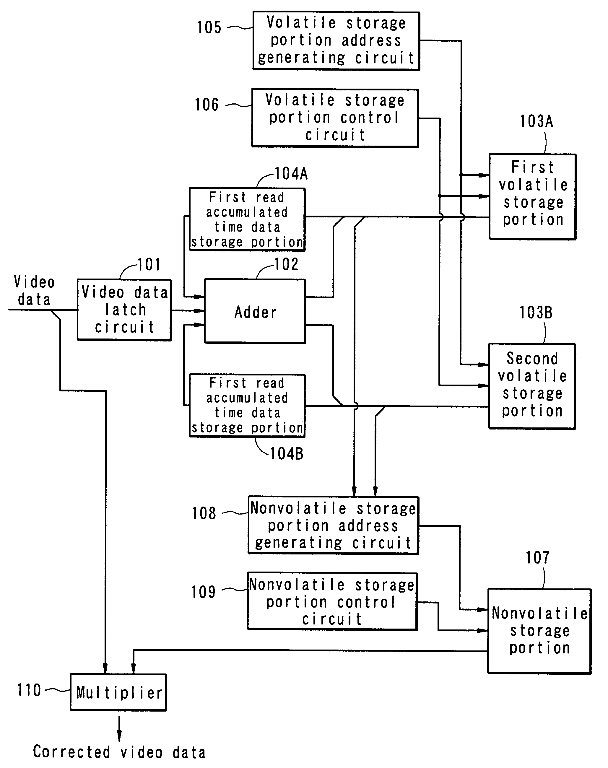
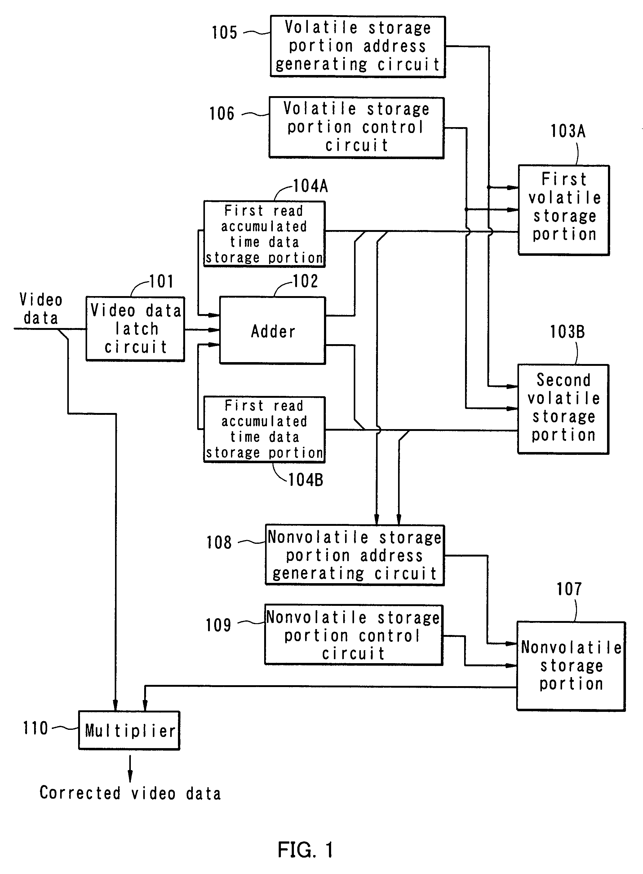
[0067]FIG. 1 is a schematic view showing a configuration example of a video data correction circuit according to the invention. The video data correction circuit includes a video data latch circuit 101 for latching video data to be sampled, an adder 102 for generating new accumulated time data by adding lighting time estimated from the sampled video data to the previous accumulated time data, a first volatile storage portion 103A and a second volatile storage portion 103B each of which is a volatile storing means for storing accumulated time data, a nonvolatile storage portion 107 that is a nonvolatile storing means for storing a degradation coefficient and creating a backup of the content of the first volatile storage portion 103A and the second volatile storage portion 103B when the power is turned off, and a multiplier 110 for generating corrected video data by multiplying the video data by a degradation coefficient corresponding to accumulated lighting time of each pixel.

[0068]A...

embodiment mode 2

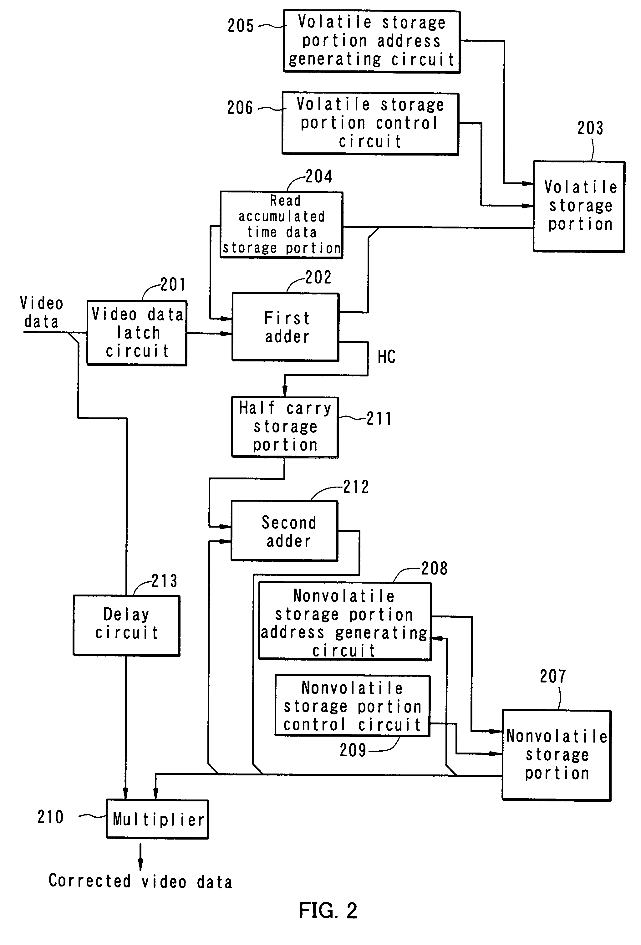
[0079]FIG. 2 is a schematic view showing a configuration example of a video data correction circuit of the invention, which is different than the one shown in Embodiment Mode 1. The video data correction circuit shown in Embodiment Mode 2 has a similar configuration to the one shown in Embodiment Mode 1, except in that only one volatile storage portion is provided to store the lower bit and half carry of accumulated time data and the upper bit of the accumulated time data is stored in the remaining address area of a nonvolatile storage portion.

[0080]The configuration and operation of the video data correction circuit according to this embodiment mode are described more specifically with reference to FIG. 2. The video data correction circuit includes a video data latch circuit 201 for latching video data to be sampled, which functions as a lighting time accumulated portion, a volatile storage portion 203 for storing the lower bit and half carry (one or more bits) of accumulated time ...

embodiment mode 3

[0092]In this embodiment mode, the lower bit of accumulated lighting time data produced by a video data correction circuit is stored in an unused address area of a storing means such as a video memory used in a display control circuit, while the upper bit of the accumulated lighting time data is stored in a nonvolatile storing means, and the data is read as needed to correct video data. That is to say, the video data correction circuit described in Embodiment Modes 1 and 2 is integrated with a control circuit of a display device. Note that the control circuit of a display device converts the format of a received video signal to be able to perform gray scale display in pixels of a display panel, writes the converted video data to a storing means, and outputs to the display panel a panel control signal and the video data read from the storing means for displaying images.

[0093]FIG. 3 is a schematic view of an integrated control circuit where a video data correction circuit of the inven...


PUM


Abstract

Accumulated usage data of each pixel of the correction circuit is divided into a plurality of data portions, each of which is stored in a different storing means. For example, the accumulated usage data is divided into the upper bit and the lower bit to be stored separately, and the upper bit of the accumulated usage data is obtained by adding the upper bit to a half carry generated by the calculation of the lower bit of the accumulated usage data. A degradation coefficient selected based on the thus obtained accumulated usage data is multiplied by video data to obtain corrected video data. The invention also provides a control circuit of a display device integrated with such a correction circuit.

Description

BACKGROUND OF THE INVENTION[0001]1. Field of the Invention[0002]The present invention relates to a display device using a light emitting element in a pixel portion. More particularly, the invention relates to a display device using a light emitting element typified by an organic electroluminescence (EL) element in a pixel portion and having a video data correction circuit for correcting video data in accordance with the degradation of the light emitting element. Further, the invention relates to a display device that has a display panel where a light emitting element such as an EL element is provided in each pixel, a control circuit having a storing means for storing video data, and a video data correction circuit for correcting the degradation of the light emitting element.[0003]2. Description of the Related Art[0004]As a substitute for an LCD (Liquid Crystal Display), there is a display device that is constituted by a display panel having a light emitting element in each pixel and...

Claims


Application Information

Patent Timeline
Patent Type & Authority Patents(United States)
IPC IPC(8): G09G3/30H05B44/00
CPCG09G3/20G09G3/3208G09G2320/0285G09G2320/048G09G3/30
Inventor OZAKI, TADAFUMI
Owner SEMICON ENERGY LAB CO LTD
Why Eureka
Try Eureka