Enclosed solar collector

a solar collector and solar energy technology, applied in solar heat collector controllers, thermal-pv hybrid energy generation, navigation instruments, etc., can solve the problem of insufficient development of efficient collectors, and achieve the effect of optimizing the conversion of solar energy

Active Publication Date: 2010-02-23
SUNTRAC INC
View PDF50 Cites 9 Cited by
  • Summary
  • Abstract
  • Description
  • Claims
  • Application Information

AI Technical Summary

Benefits of technology

[0009]A solar collector in accordance with the present invention includes a plurality of elongated linear reflectors of parabolic transverse cross-section having liquid-carrying tubes and / or strips of solar cell material extending along the axis of generation of the parabola. The elongated parabolic reflectors are mounted to a linkage system so they can be incrementally pivoted in unison through the course of a day to remain perpendicular to the rays of the sun for optimal transfer of solar energy to the axis of generation of the reflectors. A motor is operatively connected to the linkage, and a solar switch to the motor so that as the sun traverses the sky from east to west during the course of a day, the solar switch is energized and de-energized to energize and de-energize the motor, which through the linkage pivots the parabolic reflectors to remain perpendicular to the sun. The parabolic reflectors and the linkage system are mounted in an enclosed glass-topped box to further retain the heat from the sun and optimize the conversion of the solar energy to thermal or electrical energy.

Problems solved by technology

While many systems have been developed for collecting and transferring energy generated by the sun, efficient collectors have not been developed where a plurality of parabolic reflectors mounted to follow the sun are enclosed in a glass-topped box.

Method used


Image

  • Enclosed solar collector
  • Enclosed solar collector
  • Enclosed solar collector

Examples


Embodiment Construction

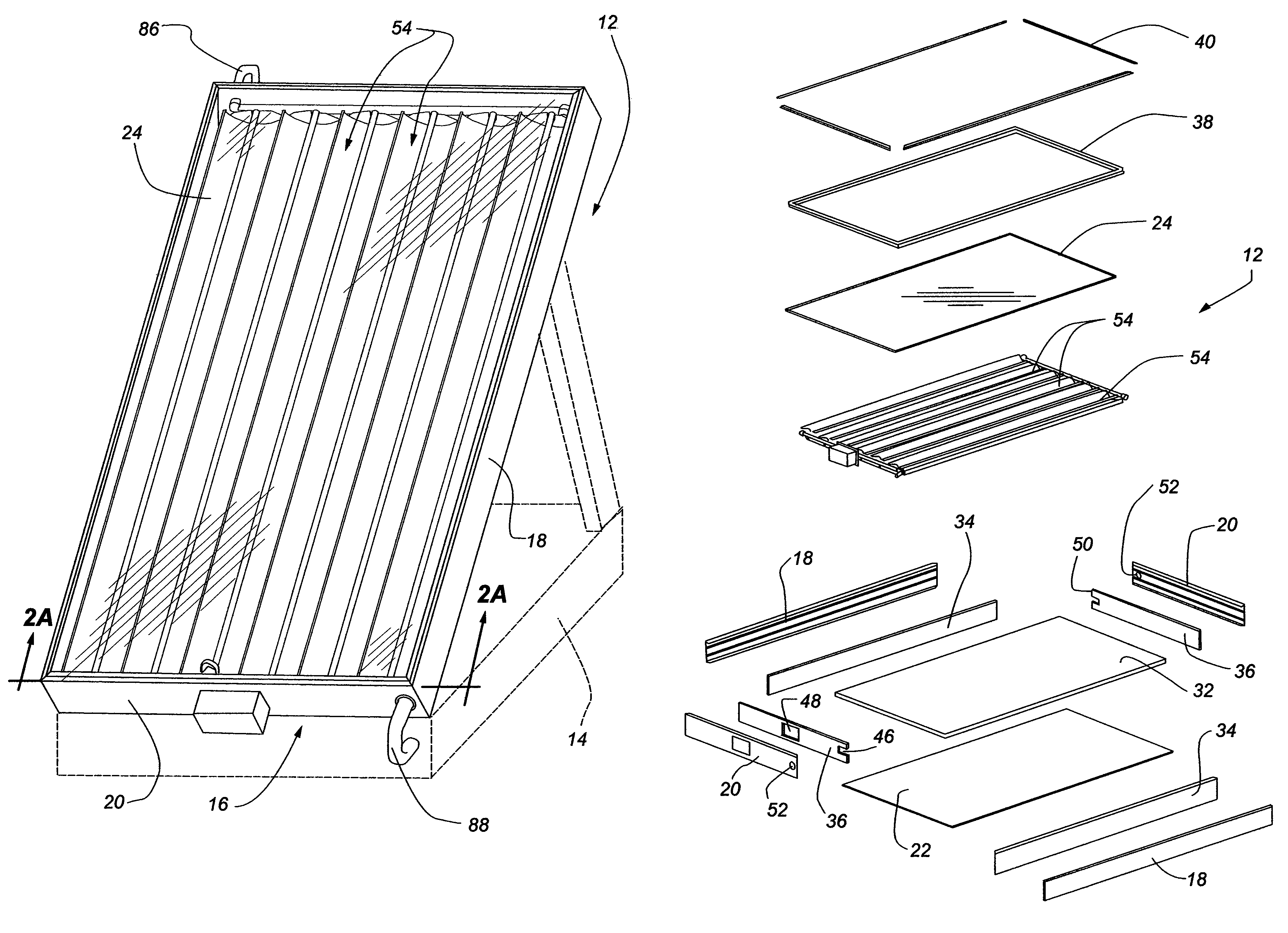
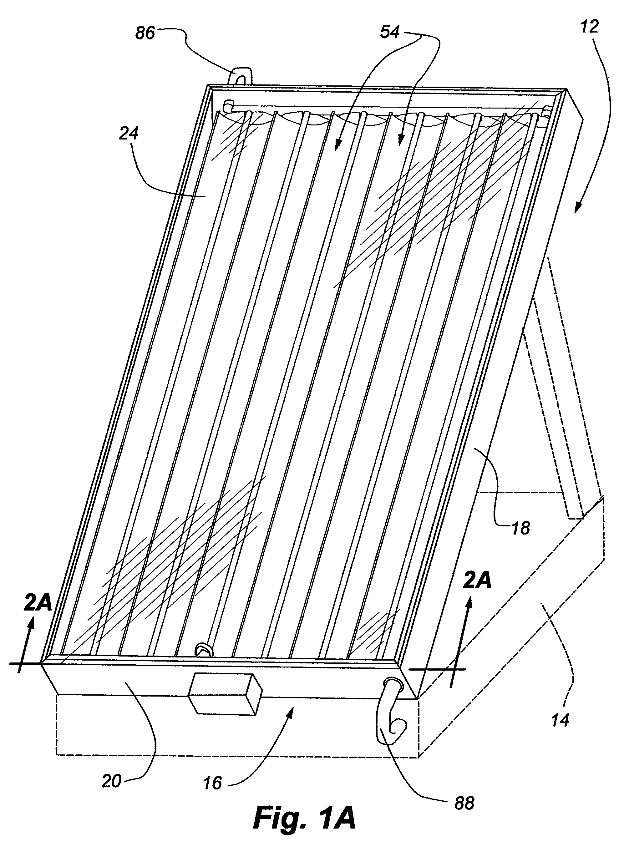
[0031]The solar collector 12 of the present invention can be seen in FIG. 1A mounted on an adjustable base 14 shown in dashed lines. The base does not form part of the present invention and could be any suitable base, which could be used to optimally position the collector for receipt of radiation from the sun.

[0032]With reference to FIGS. 1A and 1B, the solar collector 12 can be seen to include an enclosed box 16 having side walls 18, end walls 20 and a bottom wall 22. The walls of the box are all made of a suitable material, preferably aluminum and a top for the box is made of a transparent glass panel 24. The walls and the top are interconnected to define a substantially thermally sealed box. The side walls and end walls, which can also be seen in FIG. 4, for example, are of identical cross-section and made of an extruded material such as aluminum that is somewhat channel shaped having upper 26 and lower 28 inwardly directed flanges and longitudinally extending C-shaped channels ...


PUM


Abstract

A solar collector includes a plurality of elongated parabolic reflectors mounted within a glass-topped enclosure for pivotal movement such that each reflector is incrementally pivoted throughout the course of a day to remain substantially perpendicular to the sun. The incremental pivotal movement is caused by a motor energized from a solar switch having solar cells that also pivot throughout the day so that in one position of the switch, no electricity is being generated and transferred to the motor, but in a second position, the switch receives solar radiation and energizes the motor to again incrementally pivot each reflector along with the solar switch. The reflectors are therefore incrementally pivoted throughout the course of a day to follow the sun for optimal collection of solar radiation which is used to heat liquid carried by tubes positioned at the axis of generation of the parabolic reflectors and / or strips of solar cell material so that electricity can be generated alone, liquid heated alone, or liquid heated and electricity generated simultaneously.

Description

BACKGROUND OF THE INVENTION[0001]1. Field of the Invention[0002]The present invention relates generally to solar collectors and more particularly to an enclosed solar collector having a plurality of pivotal parabolic reflectors with systems mounted along their axis of generation for converting solar radiation to heated liquid and / or electricity. The parabolic reflectors are connected together with linkage for unitary pivotal movement so as to follow the course of the sun and a solar switch is utilized for incrementally driving a motor to maintain a perpendicular relationship of the reflectors with the sun. The entire system is mounted within an enclosed box with a glass top.[0003]2. Description of the Relevant Art[0004]Systems for harnessing the energy generated by the sun have been investigated for many years, and in recent years, collectors have been developed for capturing solar energy so that heat transfer fluids can be heated within the collector and transferred to other locati...

Claims


Application Information

Patent Timeline
Patent Type & Authority Patents(United States)
IPC IPC(8): F24J2/12F24J2/04F24J2/24F24J2/06F24J2/10F24S10/70F24S23/00F24S23/70F24S23/71F24S23/74F24S50/20
CPCF24J2/14F24J2/38F24J2/5413H01L31/0547H02S20/00F24J2002/1061F24J2002/5468Y02E10/45Y02E10/47Y02E10/52Y02B10/20Y02E10/60H02S40/44F24S30/428F24S23/74F24S50/20F24S2023/84F24S2030/136Y02E10/40
Inventor LOWSTUTER, JR., WILLIAM R.
Owner SUNTRAC INC
Why Eureka
Try Eureka