Arrangement for assembling products in batches on high-speed conveyor belt
Inactive Publication Date: 2010-02-23
SIDEL PARTICIPATIONS SAS
View PDF8 Cites 23 Cited by
Summary
Abstract
Description
Claims
Application Information
AI Technical Summary
This helps you quickly interpret patents by identifying the three key elements:
Problems solved by technology
Method used
Benefits of technology
Benefits of technology
[0031]when the two drive belts are in the passive state, the waiting positions of the catches of the first drive belt are offset with respect to the waiting positions of the catches of the second drive belt, so as to prevent the crossing of the catches of the two belts;
Problems solved by technology
This type of phasing device is not entirely satisfactory, since it requires the use of a plurality of conveyor belts placed end to end, giving rise to problems in respect of the overall longitudinal dimension of the installation.
Furthermore, the suction device does not operate for certain types of products, and this limits the field of application of this phasing device.
Additionally, because of its design, this phasing device cannot be used for processing products at very high speeds, for example at speeds of more than 900 products per minute.
Method used
Image
Click on the blue label to locate the original text in one second.
Reading with bidirectional positioning of images and text.
Examples
first embodiment
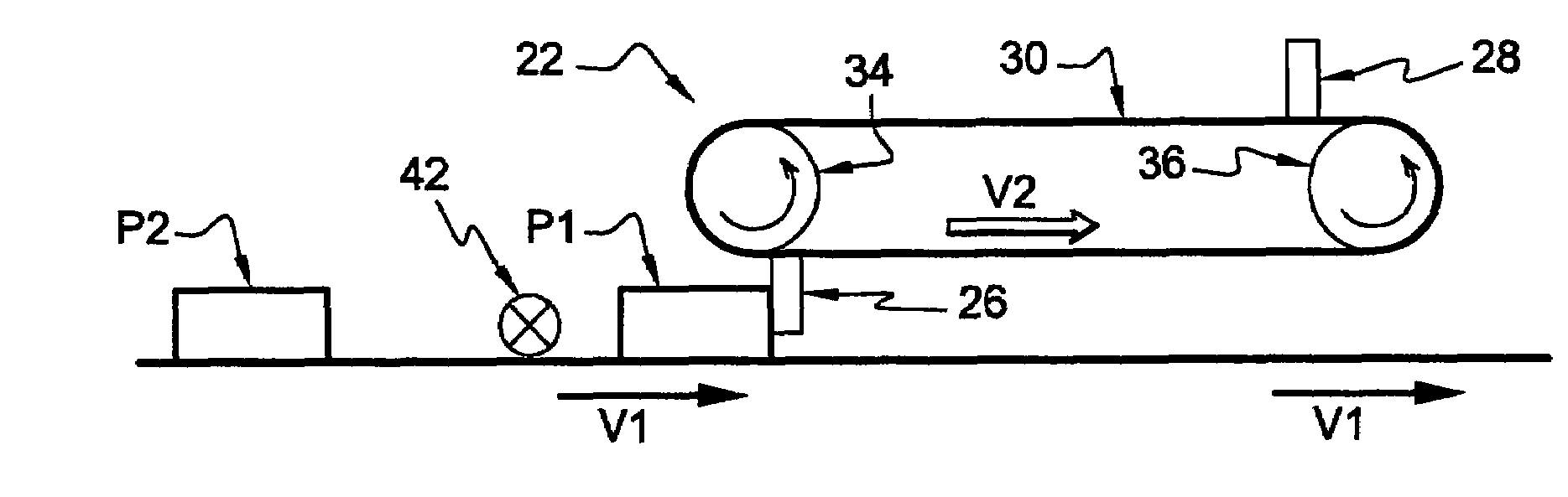
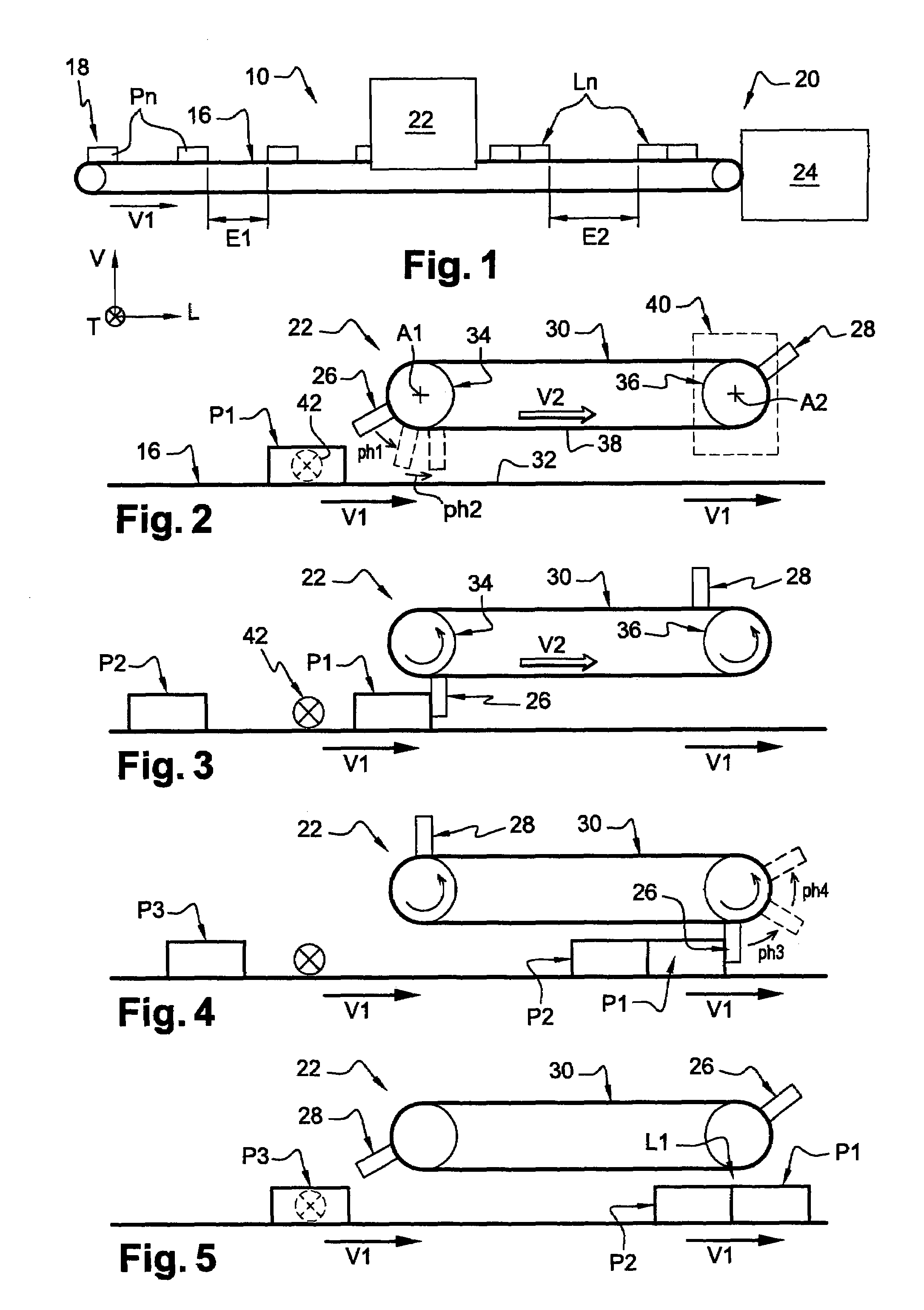
[0061]the phasing device 22 is shown schematically in FIGS. 2 to 5.
[0062]In this case, the phasing device 22 has a drive belt 30 which is placed above the upper face 32 of the belt 16 and which can move two catches 26, 28.
[0063]The belt 30 is wrapped around an upstream pulley 34 and a downstream pulley 36 with axes A1, A2, which are transverse with respect to the longitudinal direction.
[0064]In this case, the two pulleys 34, 36 are placed above the belt 16 in such a way that the lower branch 38 of the belt 30 extends substantially parallel to the upper face 32 of the belt 16, and in such a way that the catches 26, 28 are substantially centered transversely with respect to the belt 16.
[0065]The downstream pulley 36 is designed to be rotated by a servomotor 40 in such a way that the belt 30 is made to rotate around the pulleys 34, 36, and in such a way that the lower branch 38 moves in the same direction as the belt 16. For this purpose, the downstream pulley 36 is rotated in the anti...
second embodiment
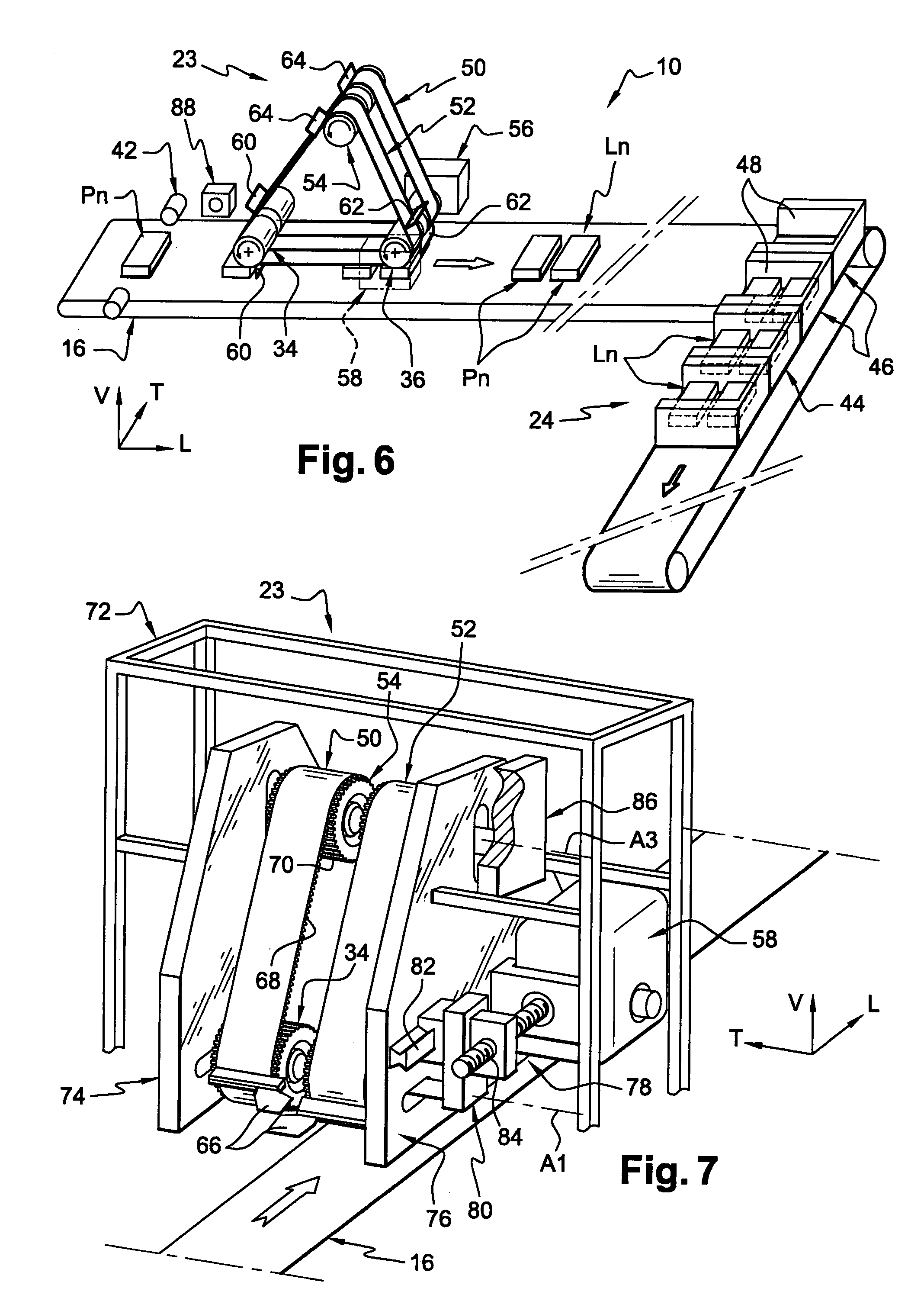
[0119]the arrangement 10 according to the invention, including an improved phasing device 23, will now be described with reference to FIGS. 6 to 12.
[0120]The phasing device 23 differs from that of the first embodiment principally in that it has two similar belts 50, 52 placed in parallel, and in that each belt 50, 52 is wrapped around a third pulley 54 which is placed above the associated lower branch 38 and above the associated upstream pulley 34 and downstream pulley 36.
[0121]In FIGS. 8 to 12, the two belts 50, 52 are shown superimposed.
[0122]The first belt 50 and the second belt 52 are placed side by side, in a substantially symmetrical way with respect to a longitudinal vertical plane of symmetry forming a median plane for the belt 16.
[0123]The first belt 50 and the second belt 52 are driven independently, by a first servomotor 56 and a second servomotor 58 respectively.
[0124]In this case, each belt 50, 52 has a first catch 60, a second catch 62, and a third catch 64, which are ...
PUM
Abstract
An arrangement (10) for assembling into batches (Ln), via a phasing device (23), a plurality of products (Pn) traveling on a conveyor belt (16) from an intake zone upstream to an exit zone downstream. The phasing device (23) is placed between the intake zone and the exit zone. The arrangement has at least one retractable catch (60, 62, 64), and the catch (60, 62, 64) is moved successively into an engaged position, causing a first product (Pn) to be slowed down until a second product (Pn) located immediately upstream moves up to it, so as to form a batch (Ln), and into a retracted position which enables the previously formed batch (Ln) to continue its downstream movement at the running speed of the belt.
Description
BACKGROUND OF THE INVENTION[0001]1. Field of the Invention[0002]The invention relates to an arrangement for assembling products in batches.[0003]The invention relates more specifically to an arrangement for assembling a plurality of products in the form of batches, the arrangement being of the type in which the products are transported on at least one conveyor belt which runs in a longitudinal direction from an intake zone upstream to an exit zone downstream, at a specified speed known as the running speed, in which the products arrive with a specified upstream spacing between two products, and of the type which has a phasing device which is placed on the path of the products so as to form batches of at least two products.[0004]2. Description of the Related Art[0005]This type of arrangement is used in product packaging installations, for example in installations having a conveyor line which conveys the products to a box filling machine which stacks batches of products in packaging c...
Claims
Application Information
Patent Timeline
Application Date:The date an application was filed.
Publication Date:The date a patent or application was officially published.
First Publication Date:The earliest publication date of a patent with the same application number.
Issue Date:Publication date of the patent grant document.
PCT Entry Date:The Entry date of PCT National Phase.
Estimated Expiry Date:The statutory expiry date of a patent right according to the Patent Law, and it is the longest term of protection that the patent right can achieve without the termination of the patent right due to other reasons(Term extension factor has been taken into account ).
Invalid Date:Actual expiry date is based on effective date or publication date of legal transaction data of invalid patent.

