Articulating dental operatory light

a dental operatory and light technology, applied in the field of electric lighting fixtures, can solve the problems of cumbersome handling, uncomfortable heat for users, and inability to adjust the position of the operator, so as to reduce the size, weight and the number of parts required, and prevent damage to the internal wiring. , the effect of reducing the size and weigh

Inactive Publication Date: 2010-02-23
WHITMAN RICK
View PDF17 Cites 15 Cited by
  • Summary
  • Abstract
  • Description
  • Claims
  • Application Information

AI Technical Summary

Benefits of technology

[0009]The above-described problems are solved and a technical advance achieved by the present articulating dental operatory light. The present light provides a compact and durable design with improved features for reducing size, weight and the number of parts required for manufacturing. Its features, particularly an improved articulating drop knuckle assembly with a rotational stop for prevention of damage to internal wiring with one or more joints at the attachment of the lamp head assembly, offer numerous advantages over traditional dental or diagnostic operatory lighting systems. The advantages stem mostly from simplification of construction using common materials and from design features that minimize the number of working parts, extend the useful life of the light, and allow maximal adjustment of the light, greatly contributing to performance and value to users.
[0010]An articulating dental operatory light is disclosed having an electrically powered light source and a mounting system with at least one ball and socket joint for multi-axial and multi-directional positioning of the light and a rotational stop for preventing damage to electrical wires passing through the ball and socket joint. The rotational stop comprises a keyed shaft containing the electrical wires, that cooperates with the ball member of the joint, and a first stop member connected to a remote end of the keyed shaft that interferes with a second stop member, thereby preventing a full 360 degree rotation of the ball member relative to the socket member of the joint and minimizing twisting damage to the electrical wires.
[0011]The articulating dental operatory light is also disclosed having an electrically powered light source and a mounting system with two joints, including a ball and socket joint and another pivoting joint, at the attachment of the lamp head assembly to a drop knuckle assembly for even greater multi-axial and multi-directional positioning and adjusting of the light, and a rotational stop for preventing damage to electrical wires passing through the joints.

Problems solved by technology

A problem remains in that heat typically radiates through all portions of the lamp head assembly, including the handles, which can get uncomfortably hot for a user.
Larger lamp heads require more substantial arms and booms to support and maintain positioning of the added weight and are cumbersome for swift handling.
A problem exists in that heat from the lamp head radiates through the lamp head housing, consequently into adjoining knuckle and arm members.
Temperature extremes are well known to cause structural changes in previously known knuckle couplers, resulting in fatigue.
The repeated fatigue from extreme temperature changes ultimately results in failure in ability to maintain sufficient friction and sustain functionality between moving parts that would otherwise keep the lamp head in a desired position.
This problem is exacerbated when temperature extremes are combined with usual wear and tear associated with routine manipulation and repeated adjustment of the lamp head, and knuckle and arm members.
Repeated movement of the light with wiring passing through the interior space of the mounting system results in shearing or internal breakdown of conductors within the wire of electrical cables which can render the light inoperable and also present a fire hazard.

Method used


Image

  • Articulating dental operatory light
  • Articulating dental operatory light
  • Articulating dental operatory light

Examples


Embodiment Construction

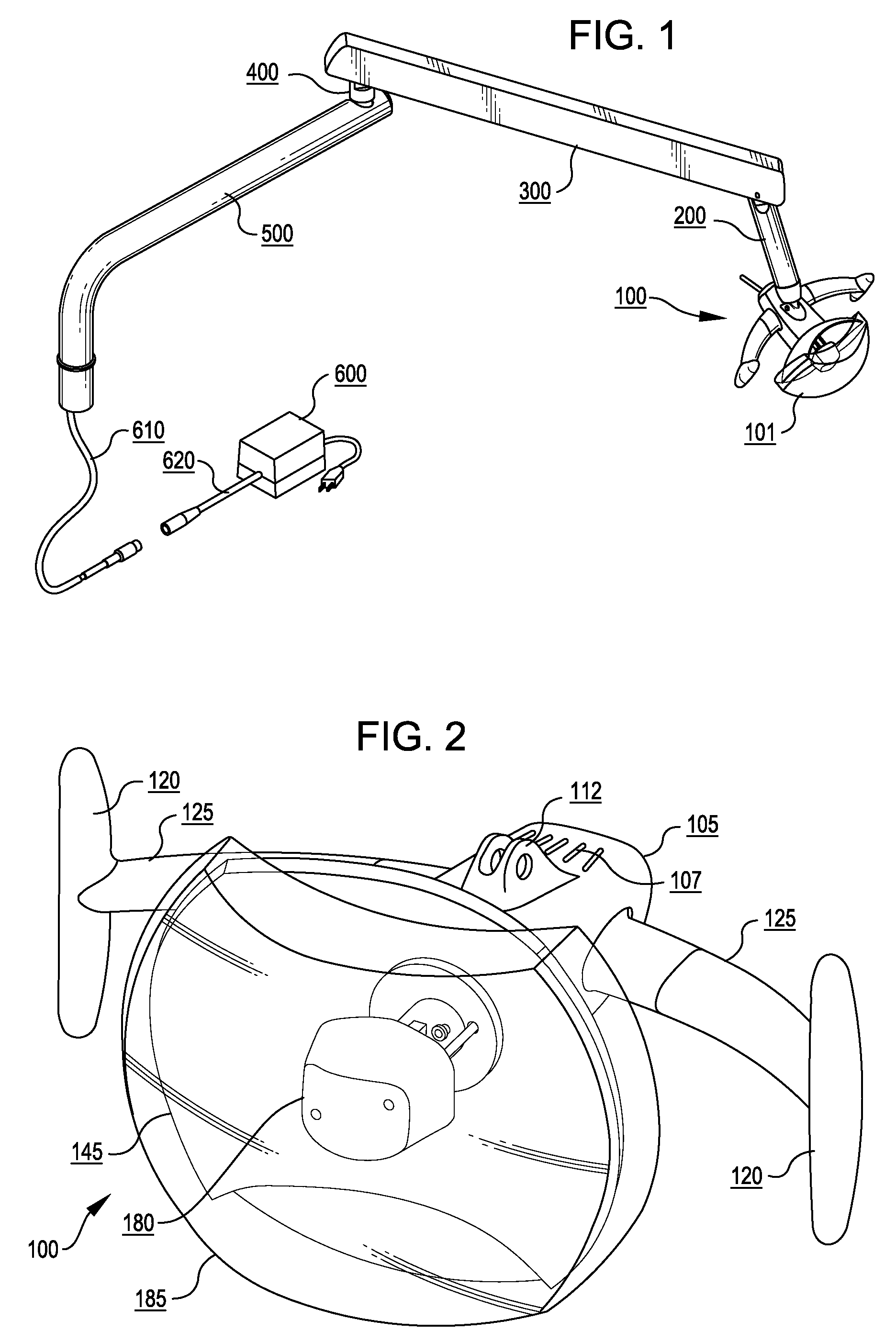
[0025]FIG. 1 shows an example of a complete dental operatory light having a lamp head assembly 100 providing a light source 101 supported on a drop knuckle assembly 200, which is in turn attached to a flex arm assembly 300. The flex arm assembly 300 is attached to a rigid knuckle assembly 400, which is then attached to a rigid arm assembly 500. The rigid arm assembly 500 is mountable to any supporting base, such as a floor stand, wall mount, table mount, floor mount, or equipment mount as is commonly known and understood in a dental operatory setting. Also shown in FIG. 1 is an electrical cable 610 that is connectable to a transformer cable 620, which feeds electrical current from an A.C. powered electrical power transformer 600.

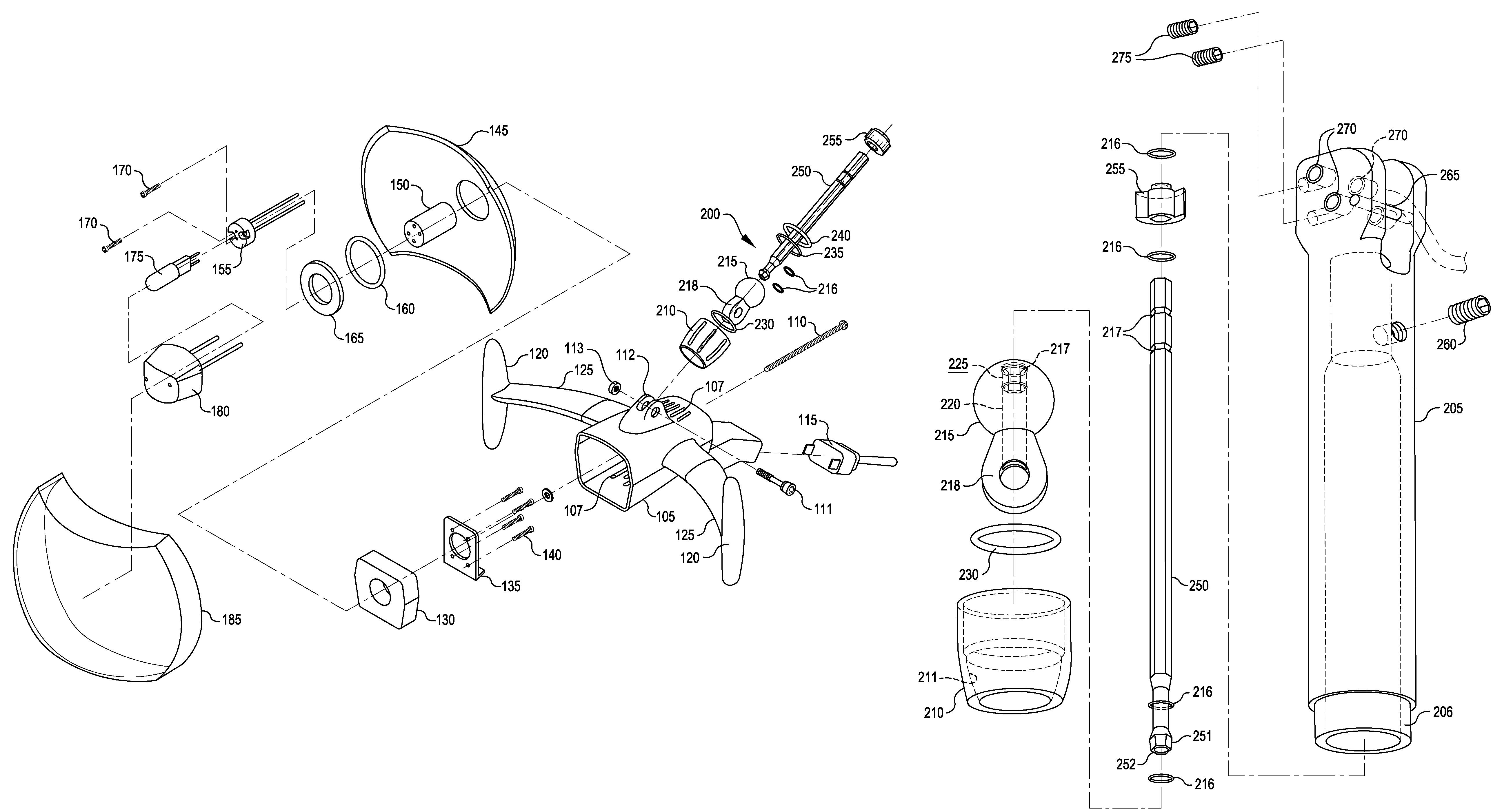
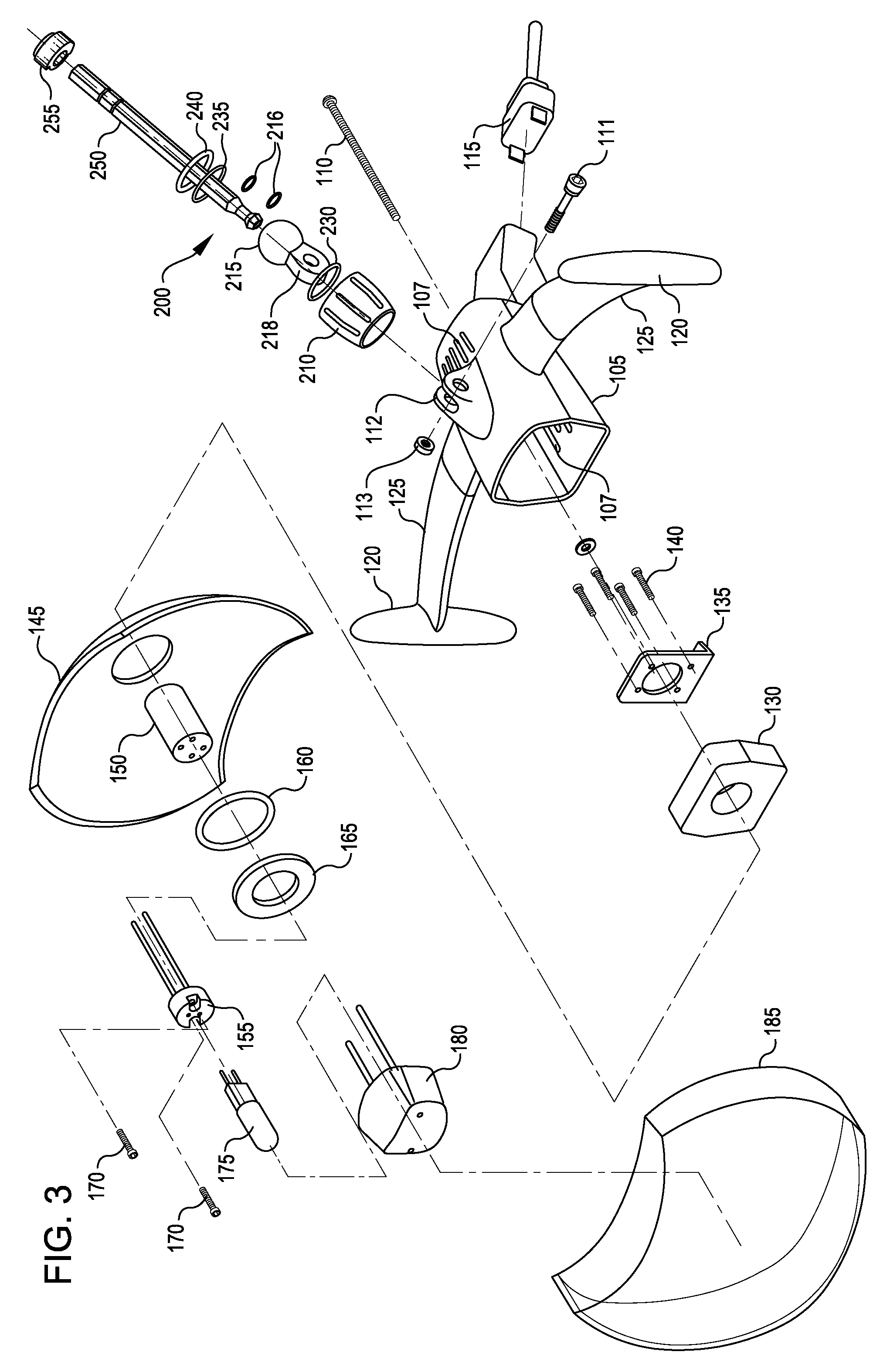
[0026]FIG. 2 shows an example of a complete lamp head assembly 100. A lamp housing 105 is provided that can be cast of metal or other heat-resistant material, molded in a single piece to simplify construction. Vent openings 107 are molded or machined into th...


PUM


Abstract

An articulating dental operatory light having an electrically powered light source and a mounting assembly with at least a ball and socket joint, and optionally an additional joint, for multi-axial and multi-directional positioning and adjusting of the lamp head assembly, and a rotational stop for preventing damage to electrical wires passing through the joints. The rotational stop comprises a keyed shaft containing the electrical wires, that cooperates with the ball portion of the joint, and a first stop member connected to a remote end of the keyed shaft that interferes with a second stop member, thereby preventing a full 360 degree rotation of the ball portion relative to the socket member of the joint and minimizing twisting damage to the electrical wires.

Description

FIELD OF INVENTION[0001]The present invention relates generally to electrical lighting fixtures. More specifically, the present invention is directed to a compact articulating dental operatory light having a mounting assembly with a ball and socket joint, and optionally additional joints, for multi-axial and multi-directional positioning and adjusting of the light, and a rotational stop for preventing damage to electrical wires passing through the joint.BACKGROUND OF THE INVENTION[0002]Lighting devices are commonly used in modern dental practice, as well as in medical, veterinary and like fields, to provide a desired pattern of illumination on an area under study or examination. The quality of the light provided is of critical importance to a user of such lighting devices, particularly when the illumination provided impacts the quality of diagnostic and treatment procedures performed on a human or animal subject. It is highly desirable to have a lighting device that provides and mim...

Claims


Application Information

Patent Timeline
Patent Type & Authority Patents(United States)
IPC IPC(8): A61B1/06
CPCF16M11/04F16M11/14F16M11/2064F21V21/29F21V27/00F21V29/15F21W2131/202F16M2200/065
Inventor WHITMAN, RICK
Owner WHITMAN RICK
Why Eureka
Try Eureka