Turbine rotor disk with dirt particle separator

a technology of dust and separator, which is applied in the field of fluid reaction surfaces, can solve the problems of low cooling potential

Inactive Publication Date: 2010-02-23
FLORIDA TURBINE TECH
View PDF16 Cites 53 Cited by
  • Summary
  • Abstract
  • Description
  • Claims
  • Application Information

AI Technical Summary

Problems solved by technology

Pressure losses associated with the cooling air in the live rim cavity as well as cross flow losses of bleeding air into the blade cooling cavities lower the useful cooling pressure whi

Method used


Image

  • Turbine rotor disk with dirt particle separator
  • Turbine rotor disk with dirt particle separator
  • Turbine rotor disk with dirt particle separator

Examples


Embodiment Construction

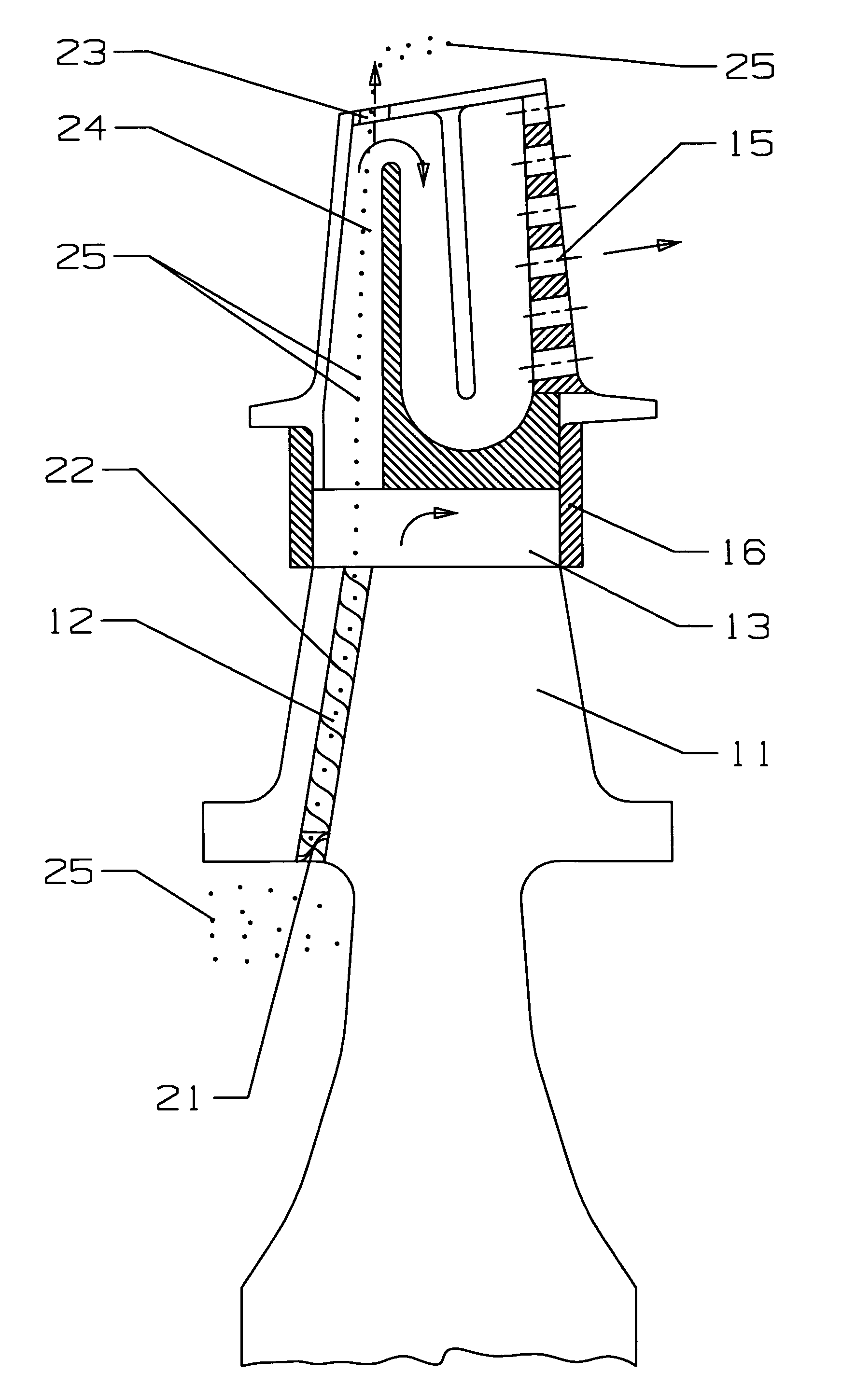
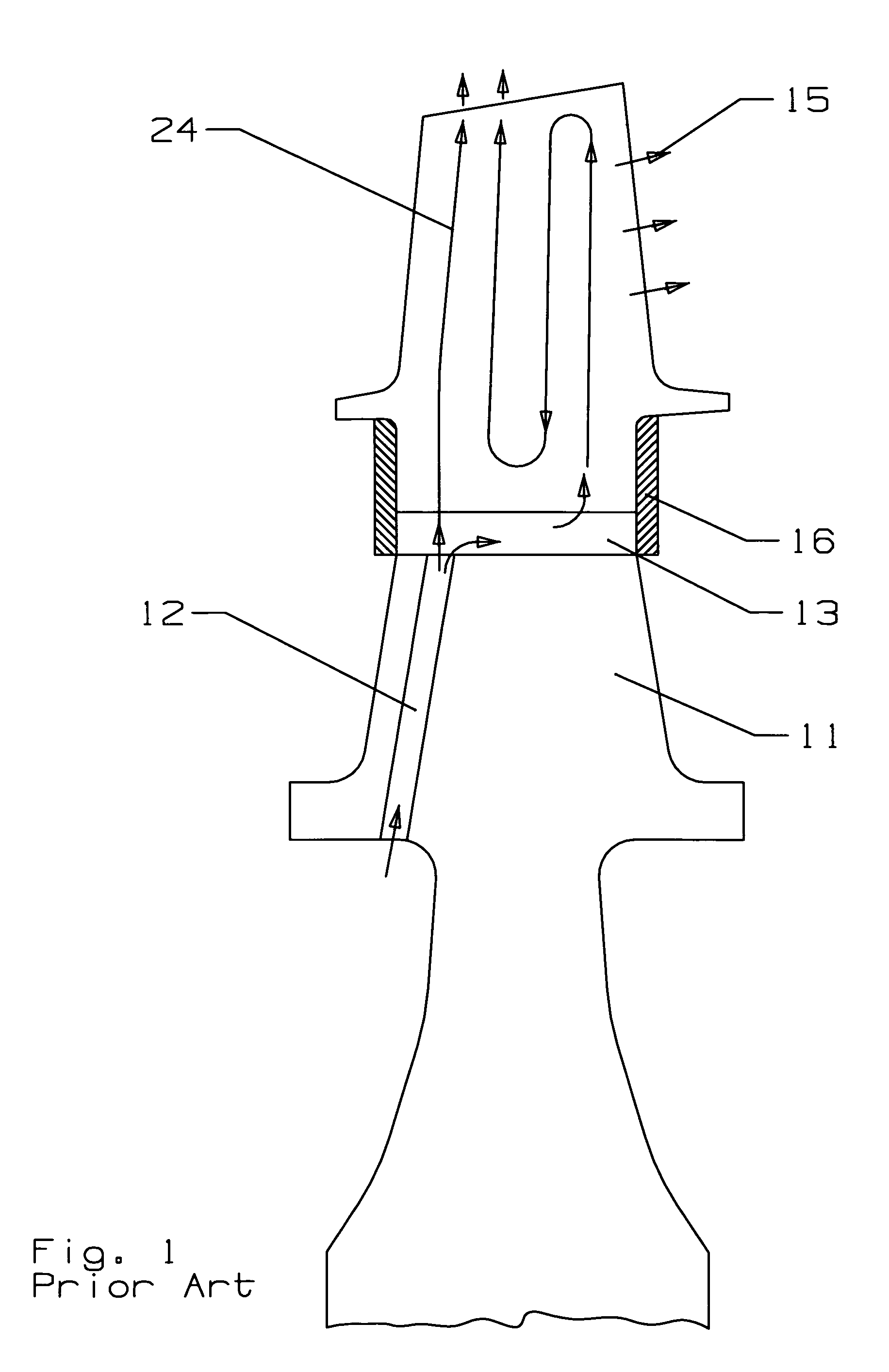
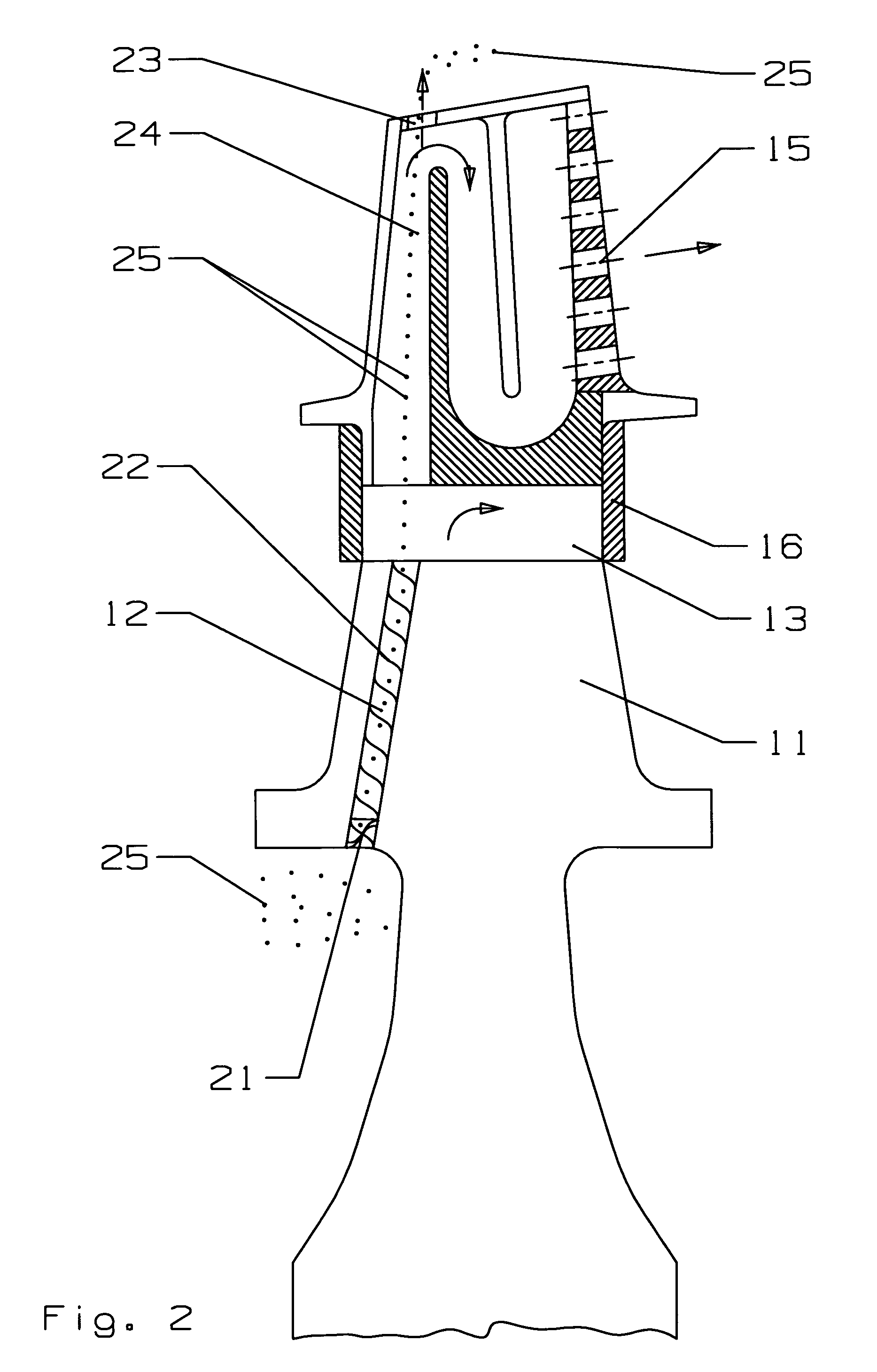
[0010]The present invention is an improvement over the prior art turbine rotor disk and blade with the cooling air feed channel in the rotor disk that feeds the cooling air into the live rim cavity and then into the cooling air passages formed within the blade. Common elements with the Prior Art FIG. 1 rotor disk are numbered as the same in the present invention of FIG. 2. In the cooling air feed channel 12, a swirl generator 21 is used to impart an initial swirl motion to the cooling air entering and passing through the feed channel 12. The swirl generator 21 in this embodiment is a twisted sheet of metal, such as an inlet guide vane, that is twisted from about 90 degrees to about 180 degrees from the inlet end to the outlet end of the swirl generator. The swirl generator 21 extends across the entire feed channel 12 in the short distance at the inlet. Any length and degree of twist can be used as long as an initial swirl is formed in the cooling air flow. Located within the remaini...


PUM


Abstract

A turbine rotor disk with a turbine blade, the rotor disk having a cooling air feed channel to force cooling air into an internal cooling air passage within the turbine blade, the feed channel including a swirl generator at the inlet end to promote a swirling motion within the cooling air, and the feed channel including a helical rib extending from the swirl generator to the outlet of the feed channel to maintain the swirling motion of the cooling air within the feed channel such that dirt particles in the cooling air are collected within the center of the swirling air flow. The feed channel directs the swirling cooling air into a first passage of the internal serpentine flow cooling circuit of the blade. A cooling air exit hole is located at the blade tip and is aligned with the cooling air flow in the first passage. The swirling air flow with the collected dirt particles ejects the dirt particles out through the exit hole while the clean cooling air continues through the serpentine flow circuit to provide cooling for the blade.

Description

BACKGROUND OF THE INVENTION[0001]1. Field of the Invention[0002]The present invention relates generally to fluid reaction surfaces, and more specifically to turbine rotor disk with a particle separator.[0003]2. Description of the Related Art including information disclosed under 37 CFR 1.97 and 1.98[0004]A prior art cooling air feed channel for a turbine blade is mounted on the side of the rotor disk and located at the entrance point of the live rim. Cooling air channels through the live rim through a cooling air feed channel and periodically bleeds off into the blade cooling cavity for use in cooling the blade. Pressure losses associated with the cooling air in the live rim cavity as well as cross flow losses of bleeding air into the blade cooling cavities lower the useful cooling pressure which translates to lower cooling potential for the use of cooling air to produce higher blade internal cooling performance and provide higher backflow margin for the blade cooling design. In add...

Claims


Application Information

Patent Timeline
IPC IPC(8): F01D5/18
CPCF01D5/18F01D25/00F05D2260/607
Inventor LIANG, GEORGE
Owner FLORIDA TURBINE TECH
Why Eureka
Try Eureka