
Laminated piezoelectric element and process for producing the same

a piezoelectric element and piezoelectric technology, applied in piezoelectric/electrostrictive/magnetostrictive devices, basic electric elements, generators/motors, etc., can solve the problem of high price of pd, achieve good piezoelectric constant, improve sinterability, and effectively charge compensation

Active Publication Date: 2010-02-23
MURATA MFG CO LTD
View PDF19 Cites 9 Cited by
  • Summary
  • Abstract
  • Description
  • Claims
  • Application Information

AI Technical Summary

Benefits of technology

[0011]On the other hand, the melting point of Cu is about 1,050° C. Since the firing temperature of 1,000° C. is close to the melting point of Cu, it is desirable to further decrease the firing temperature. Moreover, if the firing temperature is decreased, it is considered that the amount of diffusion of Cu can be reduced. From such a standpoint, it is also desirable to decrease the firing temperature. Furthermore, if the firing temperature is decreased, the energy required for firing can be reduced. Thus, fuel and electric power can be saved, and also the manufacturing cost can be reduced.
[0013]As a result of diligent studies conducted by the present inventors to achieve the object described above, it has been found that by incorporating a metal oxide in a piezoelectric ceramic such that the concentration of the metal oxide decreases with distance from internal electrode layers, it is possible to charge-compensate for the decrease in the average valence in the B site of the piezoelectric ceramic composition due to the diffusion of Cu, and thereby it is possible to obtain a satisfactory piezoelectric constant even if the donor content is not adjusted to be in excess in the B site of the piezoelectric ceramic. Moreover, since it is not necessary to set the donor content to be in excess, sinterability can be improved, and a desired multilayer piezoelectric device can be obtained by low-temperature firing.
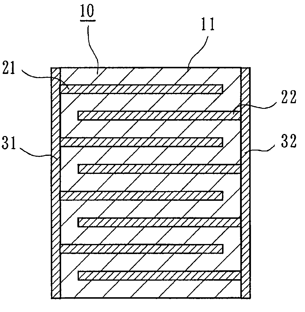
[0020]According to the multilayer piezoelectric device of the present invention, a metal oxide containing at least one of a pentavalent metal element and a hexavalent metal element (Nb, Sb, Ta, W, or the like) is incorporated in the piezoelectric ceramic layers such that the concentration of the metal oxide decreases with distance from the internal electrode layers. Consequently, the decrease in the average valence due to the diffusion of Cu can be charge-compensated for by the metal oxide, and thereby it is possible to obtain a good piezoelectric constant even if the donor content is not adjusted to be in excess to perform charge compensation. Furthermore, since it is not necessary to set the B site so that the donor content is in excess, sinterability can be improved, and firing can be performed at lower temperatures. Moreover, in the vicinity of the internal electrodes where the decrease in the average valence due to the diffusion of Cu is large, charge compensation can be effectively performed by the metal oxide. Meanwhile, in locations distant from the internal electrode layers where the decrease in the average valence due to the diffusion of Cu is not very large, since the concentration of the metal oxide is low, the metal oxide is not diffused excessively into the piezoelectric ceramic layers. Thereby, it is also possible to suppress the decrease in sinterability, thus being favorable to low-temperature firing.
[0021]Furthermore, according to the method for manufacturing the multilayer piezoelectric device of the present invention, the internal electrode patterns contain a conductive powder containing Cu and at least one of a pentavalent metal element and a hexavalent metal element (Nb, Sb, Ta, W, or the like), and in the firing step, the metal element is diffused, in the form of a metal oxide, such as Nb2O5, Sb2O5, Ta2O5, or WO3, from the internal electrode layers into the piezoelectric ceramic layers such that the concentration decreases with distance from the internal electrode layers. Consequently, a concentration gradient of the metal oxide is formed in the piezoelectric ceramic layers. Therefore, it is possible to easily fabricate a multilayer piezoelectric device in which the concentration of a metal oxide decreases with distance from internal electrode layers in piezoelectric layers, and it is possible to fabricate a multilayer piezoelectric device in which a satisfactory piezoelectric constant can be obtained even if firing is performed at low temperatures.
[0022]Furthermore, since the content of the metal oxide is less than 40.0% by weight on the basis of the total content of the conductive powder and the metal oxide, the connectivity between the internal electrode layers and external electrodes is not decreased. Thus, it is possible to obtain a high-quality multilayer piezoelectric device with high reliability.

Problems solved by technology

However, since Pd is expensive, research and development has been actively carried out on multilayer piezoelectric devices in which inexpensive Cu is used as the material for internal electrodes.

Method used


Image

  • Laminated piezoelectric element and process for producing the same
  • Laminated piezoelectric element and process for producing the same
  • Laminated piezoelectric element and process for producing the same

Examples


example 1

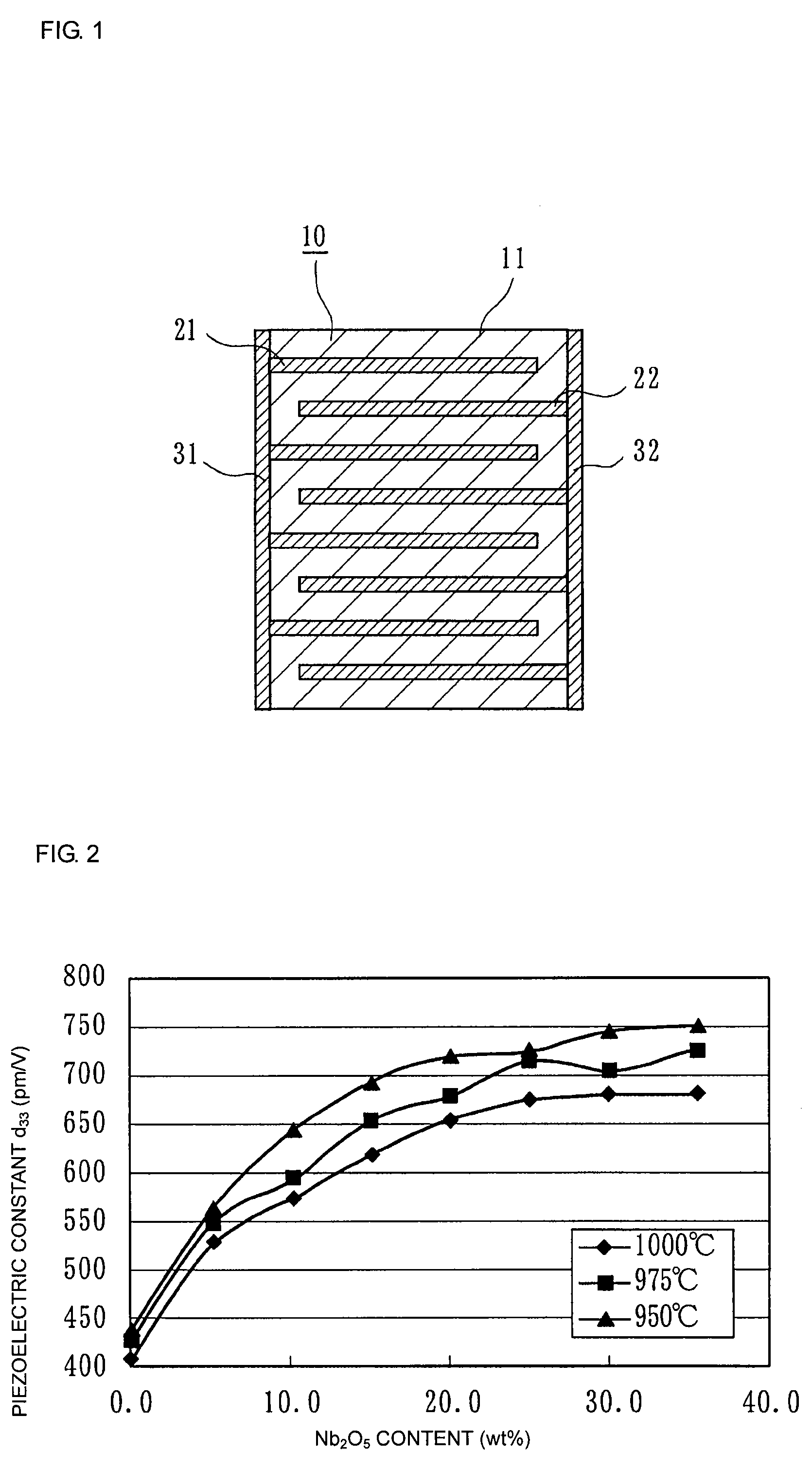
[0055]First, as starting materials for a piezoelectric ceramic, Pb3O4, TiO2, ZiO2, NiO, ZnO, and Nb2O5 powders are prepared and weighed so as to satisfy the composition shown in compositional formula (1) below.

Pb{(Ni1 / 3Nb2 / 3)0.1(Zn1 / 3Nb2 / 3)0.1Ti0.42Zr0.38}O3  (1)

[0056]The weighed starting materials were mixed and pulverized for 16 hours, and then calcined at 880° C. to obtain calcined powder of the piezoelectric ceramic. The calcined powder was kneaded with a binder and a plasticizer, and piezoelectric ceramic green sheets with a thickness of 120 μm were obtained by a doctor blade process.

[0057]Next, as conductive powders, a Cu powder and a Ni powder were prepared, and as a metal oxide containing a pentavalent metal element, Nb2O5 was prepared.

[0058]Then, the Cu powder, the Ni powder, and Nb2O5 were weighed so that the ratio of the Cu powder content to the Ni powder content, in terms of weight, was 85:15 and the Nb2O5 content was 0% to 40% by weight on the basis of the total solid c...

example 2

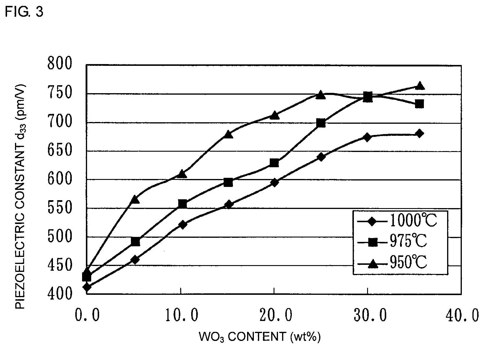
[0078]Multilayer piezoelectric devices of Sample Nos. 11a to 19c were fabricated by the same method and procedure as in [Example 1] except that WO3 containing a hexavalent metal element was used, instead of Nb2O5, as the metal oxide incorporated in the internal electrode pattern.

[0079]Next, with respect to Sample Nos. 11a to 19c, the piezoelectric constant d33 was calculated by the same method and procedure as in [Example 1]. Furthermore, with respect to the samples in each of Sample Nos. 11b, 12b, and 15b, the concentrations (contents) of WO3 and CuO were measured using a WDX (wavelength dispersive X-ray spectrometer).

[0080]Table 3 shows the WO3 content on the basis of the total solid content in the internal electrode pattern, the firing temperature, and the piezoelectric constant d33 in each sample, and Table 4 shows the concentrations of WO3 and CuO at each measuring point in the piezoelectric ceramic layer.

[0081]

TABLE 3FiringPiezoelectricSampleWO3 contenttemperatureconstant d33N...


PUM


Abstract

A multilayer piezoelectric device including a body having internal electrode layers and piezoelectric ceramic layers alternately stacked. The internal electrode layers contain Cu as a major component, the piezoelectric ceramic layers contain a compound oxide represented by Pb(Ti, Zr)O3 as a major component, and a metal oxide (Nb2O5, Sb2O5, Ta2O5, or WO3) containing Nb, Sb, Ta, or W, which is at least one of a pentavalent metal element and a hexavalent metal element, is incorporated in the piezoelectric ceramic layers such that the concentration of the metal oxide decreases with distance from the internal electrode layers. Thereby, even in a case where internal electrodes contain Cu as a major component, it is possible to provide a multilayer piezoelectric device which can be obtained by low-temperature firing while ensuring a sufficient piezoelectric constant.

Description

CROSS REFERENCE TO RELATED APPLICATIONS[0001]The present application is a continuation of International Application No. PCT / JP2006 / 320398, filed Oct. 12, 2006, which claims priority to Japanese Patent Application No. JP2005-354332, filed Dec. 8, 2005, the entire contents of each of these applications being incorporated herein by reference in their entirety.FIELD OF THE INVENTION[0002]The present invention relates to a multilayer piezoelectric device, such as a piezoelectric actuator, a piezoelectric resonator, or a piezoelectric filter, and a method for manufacturing the multilayer piezoelectric device.BACKGROUND OF THE INVENTION[0003]PZT-based piezoelectric ceramics containing Pb(Ti, Zr)O3 (hereinafter referred to as “PZT”) as a major component are widely known as typical piezoelectric ceramics used for multilayer piezoelectric devices, such as piezoelectric actuators, piezoelectric resonators, and piezoelectric filters.[0004]Furthermore, as multilayer piezoelectric devices includi...

Claims


Application Information

Patent Timeline
Patent Type & Authority Patents(United States)
IPC IPC(8): H01L41/08C04B35/491C04B41/88H01L41/083H01L41/187H01L41/22H01L41/273H01L41/297H01L41/39H01L41/43
CPCC04B35/493H01L41/083H01L41/1876H01L41/273C04B2235/3251C04B2235/3255C04B2235/3258C04B2235/3279C04B2235/3284Y10T29/42C04B2235/6025C04B2235/656C04B2235/3294H10N30/50H10N30/8554H10N30/053H10N30/85
Inventor YAMAMOTO, ATSUSHIDEGUCHI, YOICHIHAYASHI, KOICHI
Owner MURATA MFG CO LTD
Learn More