Composite Ceramic Substrate For Micro-Fluid Ejection Head

a technology of microfluid ejection head and ceramic substrate, which is applied in the direction of variable capacitor, inking apparatus, transportation and packaging, etc., can solve the problems of compromising the desired direction of fluid-jetting, ejection head, and increasing complexity, so as to improve the encapsulation of conductors, improve the effect of planarity and high resistan

Inactive Publication Date: 2008-12-04
FUNAI ELECTRIC CO LTD
View PDF18 Cites 25 Cited by
  • Summary
  • Abstract
  • Description
  • Claims
  • Application Information

AI Technical Summary

Benefits of technology

[0011]An advantage of the composite ceramic structure according to the disclosure is that a substantially planar surface of a previously fired ceramic material base may be provided for improved planarity of micro-fluid ejection head chips attached to the base. Additionally, the LTCC layer bundle provides improved encapsulation of conductors after tiring the ceramic base. Use of LTCC layers to provide the LTCC layer bundle also enables the use of relatively low resistance conductor material to provide the encapsulated conductors lines.
[0012]By comparison, micro-fluid ejection beads using substrates made of high temperature co-fired (HTCC) tape layers, as described in U.S. Patent Publication Nos. 2002 / 0033861, 2004 / 0113996, and U.S. Pat. No. 6,543,880, are fired at temperatures of about 1600° C., and thus require the use of refractory metals that have relatively high resistance. Use of the LTCC layers for encapsulating the conductors enables the use of relatively lower firing temperatures and the use of non-refractory metals for conductors. Another advantage of the LTCC layers is that LTCC materials are available that have a shrinkage rate in the X-Y plane of less than about 1%. Since the LTCC layers may be laminated to a base ceramic substrate at temperatures substantially below 1600° C., dimensional changes and / or warpage of the base ceramic and delamination between the base ceramic and LTCC layers is minimized.

Problems solved by technology

As the capabilities of micro-fluid ejection devices are increased to provide higher ejection rates, the ejection heads, which are the primary components of micro-fluid ejection devices, continue to evolve and become larger, more complex, and more costly to manufacture.
If the nozzle plate is warped or bowed, due to warping or bowing of the underlying ejection device substrate, the desired direction of fluid-jetting is compromised.
The planarity of these components may be affected by mismatched coefficients of thermal expansion between the various members of the ejection head, including the nozzle plate, the device substrate, the base support, and any adhesive material used in securing the aforementioned components to one another.
Current manufacturing processes are limited by the size of the ejection head substrate used to provide a single ejection head chip.
However, mounting multiple chips on a single substrate increases the difficulties of maintaining manufacturing tolerances.
For example, the difficulty of maintaining the planarity and manufacturing tolerances of multiple chips on a substrate is greatly increased as the number of chips on a substrate increases.
However, such adhesives require thermal curing which causes expansion and contraction of the components and may lead to warping or bowing of the ejection device substrate and the nozzle plate.
During firing, shrinkage occurs, leading to poor control over dimensional tolerances in the as-fired state.
Providing a planar die attach surface for mounting multiple chips in recessed pockets is difficult and increases the difficulty of manufacturing large, multi-chip ejection heads.

Method used


Image

  • Composite Ceramic Substrate For Micro-Fluid Ejection Head
  • Composite Ceramic Substrate For Micro-Fluid Ejection Head
  • Composite Ceramic Substrate For Micro-Fluid Ejection Head

Examples


Embodiment Construction

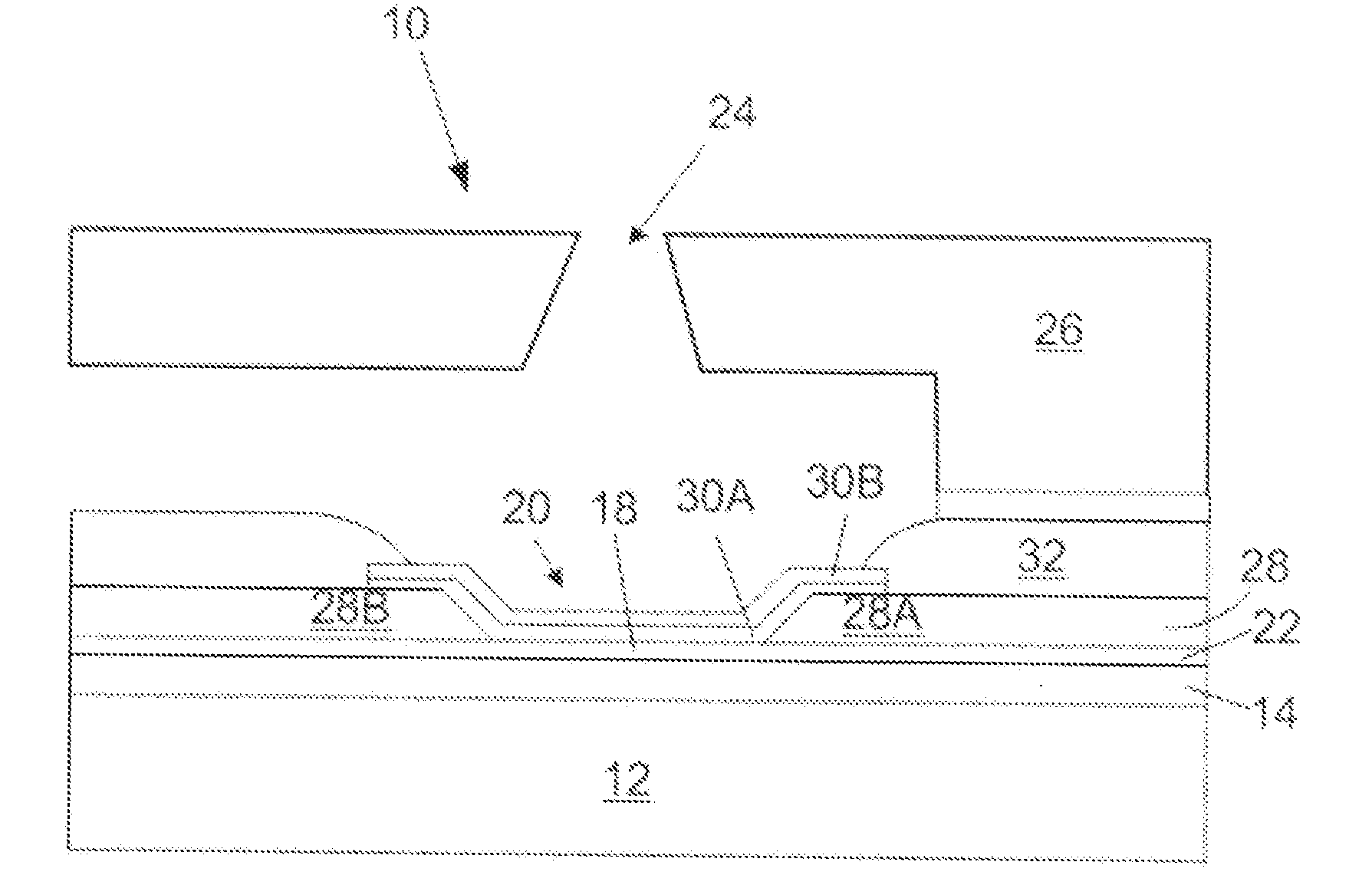
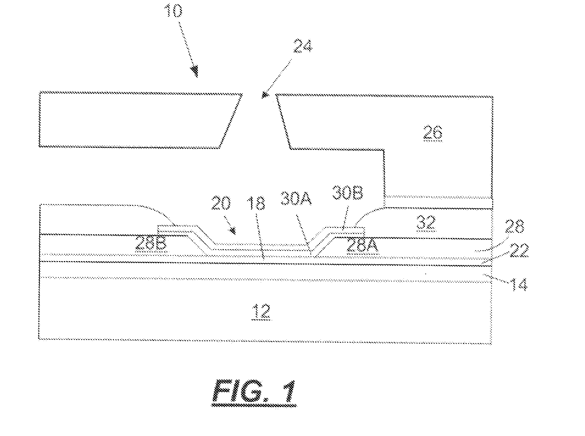
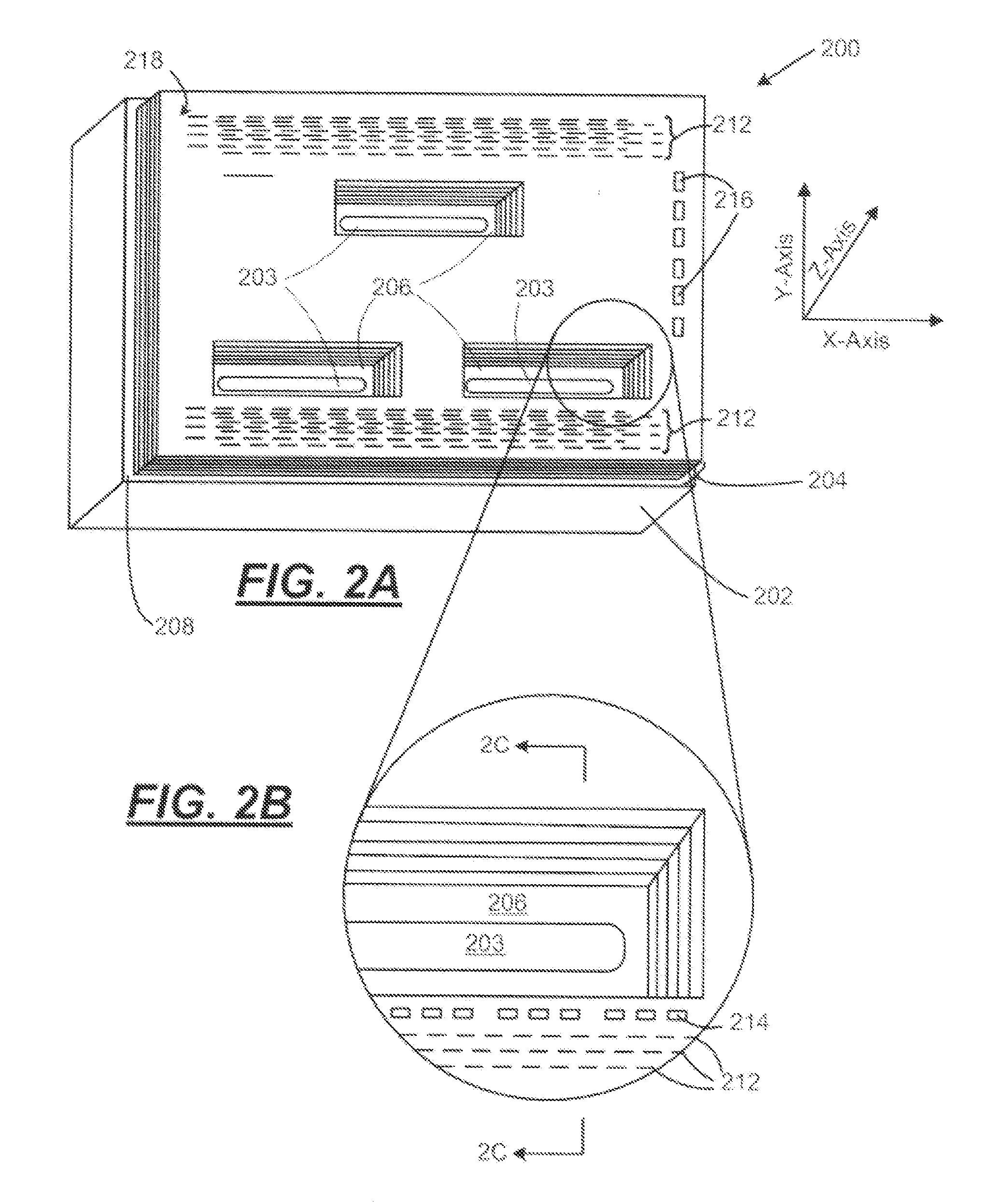
[0022]As described in more detail below, the exemplary embodiments disclosed herein relate to non-conventional substrates for providing planarized micro-fluid ejection, heads for micro-fluid ejection devices such as ink jet printers and the like. Such non-conventional substrates, unlike conventional silicon, substrates, may be used to provide large arrays of micro-fluid ejection actuators on a single substrate. For example, relatively Song composite ceramic substrates may be used to provide page wide ink jet printers and other large format fluid ejection devices.

[0023]Components of the composite ceramic structure include two or more low temperature co-fired ceramic (LTCC) tape layers and a previously fired ceramic base material. An LTCC tape layer bundle made from the LTCC tape layers also includes relatively low resistance conductors encapsulated therein to provide electrical connections for micro-fluid ejection head chips attached to the composite substrate.

[0024]Micro-fluid eject...


PUM

PropertyMeasurementUnit
weight percentaaaaaaaaaa
shrinkage rateaaaaaaaaaa
shrinkageaaaaaaaaaa

Abstract

A composite ceramic substrate for receiving an ejection head chip for a micro-fluid ejection head and a method for making the composite ceramic substrate. The substrate includes a high temperature previously fired ceramic base having a substantially planarized first surface and at least one fluid supply slot therethrough. A low temperature co-fired ceramic (LTCC) tape layer bundle having at least two LTCC tape layers is attached to the ceramic base at an interface between the LTCC tape layer bundle and the first surface of the ceramic base. The LTTC tape layer bundle has at least one chip pocket therein and at least one of the LTCC tape layers includes a plurality of conductors.

Description

FIELD OF THE DISCLOSURE[0001]The present disclosure is generally directed toward micro-fluid ejection heads. More particularly, in an exemplary embodiment, the disclosure relates to the manufacture of micro-fluid ejection heads utilizing non-conventional, ceramic substrates.BACKGROUND AND SUMMARY[0002]Multi-layer circuit devices such as micro-fluid ejection heads have a plurality of electrically conductive layers separated by insulating dielectric layers and applied adjacent to a substrate, typically a semiconductor substrate. Thermal energy generators or heating elements, usually resistors, are located on an ejection head chip and are for heating and vaporizing fluid to be ejected.[0003]Micro-fluid ejection devices such as ink jet printers continue to experience wide acceptance as economical replacements for laser printers. Micro-fluid ejection devices also are finding wide application in other fields such as in the medical, chemical, and mechanical fields. As the capabilities of m...

Claims


Application Information

Patent Timeline
Patent Type & Authority Applications(United States)
IPC IPC(8): B41J2/01
CPCB41J2/14129B41J2/1603B41J2/1628B41J2/1632B41J2/1634Y10T29/49163Y10T29/49401Y10T29/49155Y10T428/24926Y10T29/435B41J2202/03
Inventor ANDERSON, FRANK EDWARDDIXON, MICHAEL JOHNHALL, ERIC SPENCERKLEMO, ELIOSMCKINLEY, BRYAN DALESINGH, JEANNE MARIE SALDANHA
Owner FUNAI ELECTRIC CO LTD
Why Eureka
Try Eureka