Sensor malfunction determination device and sensor malfunction determination method
a technology of malfunction determination and sensor, which is applied in the direction of instruments, nuclear elements, tractor, etc., can solve the problem of not being able to inspect the pressure sensor
- Summary
- Abstract
- Description
- Claims
- Application Information
AI Technical Summary
Benefits of technology
Problems solved by technology
Method used
Image
Examples
first embodiment
Configurations of Pneumatic Tire and Rim Wheel
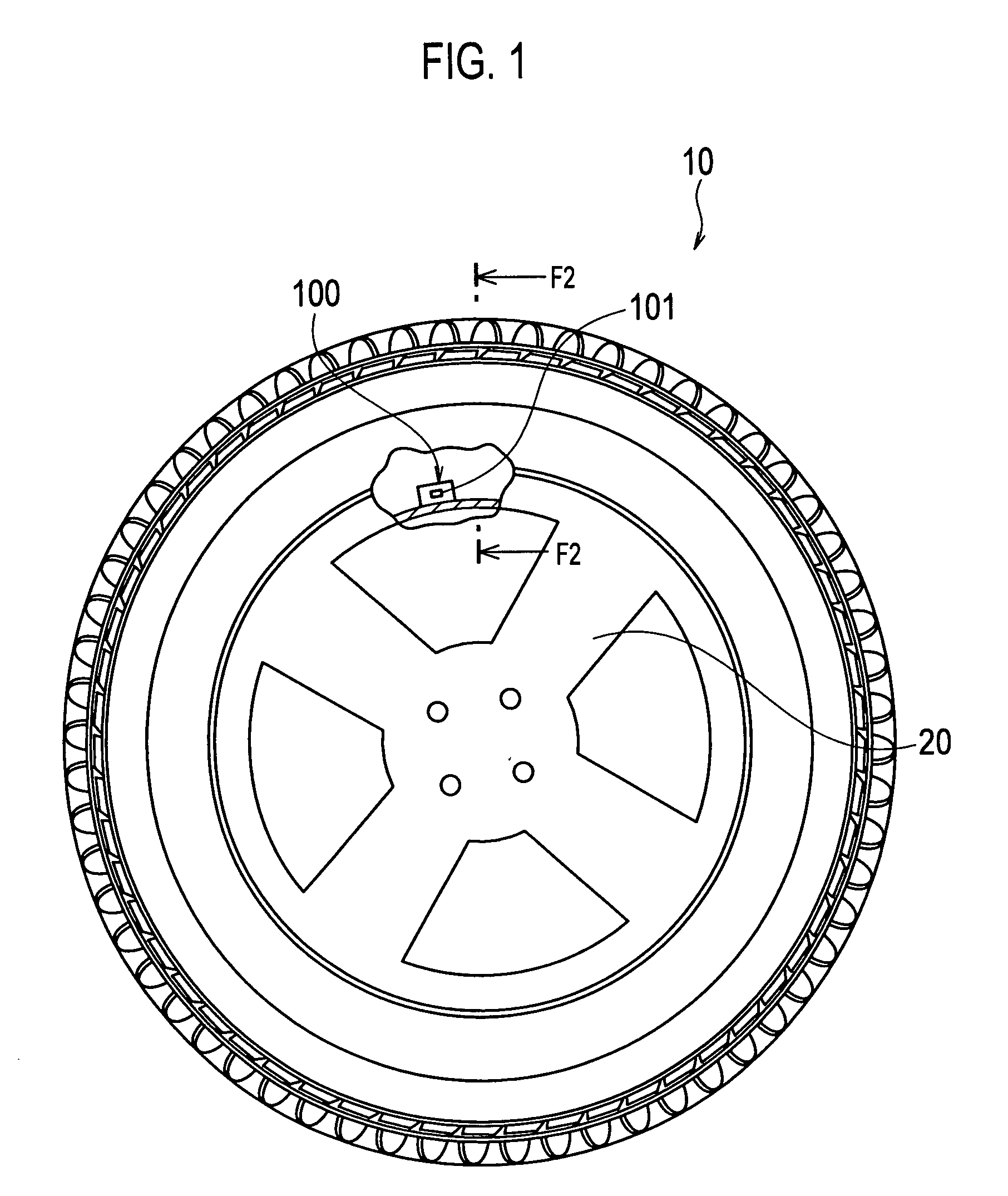
[0028]FIG. 1 is a side view of a pneumatic tire 10, and also includes a partially transparent side view of a rim wheel 20. As shown in FIG. 1, a tire data transmission device 100 is provided to the rim wheel 20 on which the pneumatic tire 10 is mounted.
[0029]The tire data transmission device 100 is provided with a pressure sensor 101 capable of measuring the internal pressure of the pneumatic tire 10, as will be described later.
(Configuration of Tire Data Transmission Device)
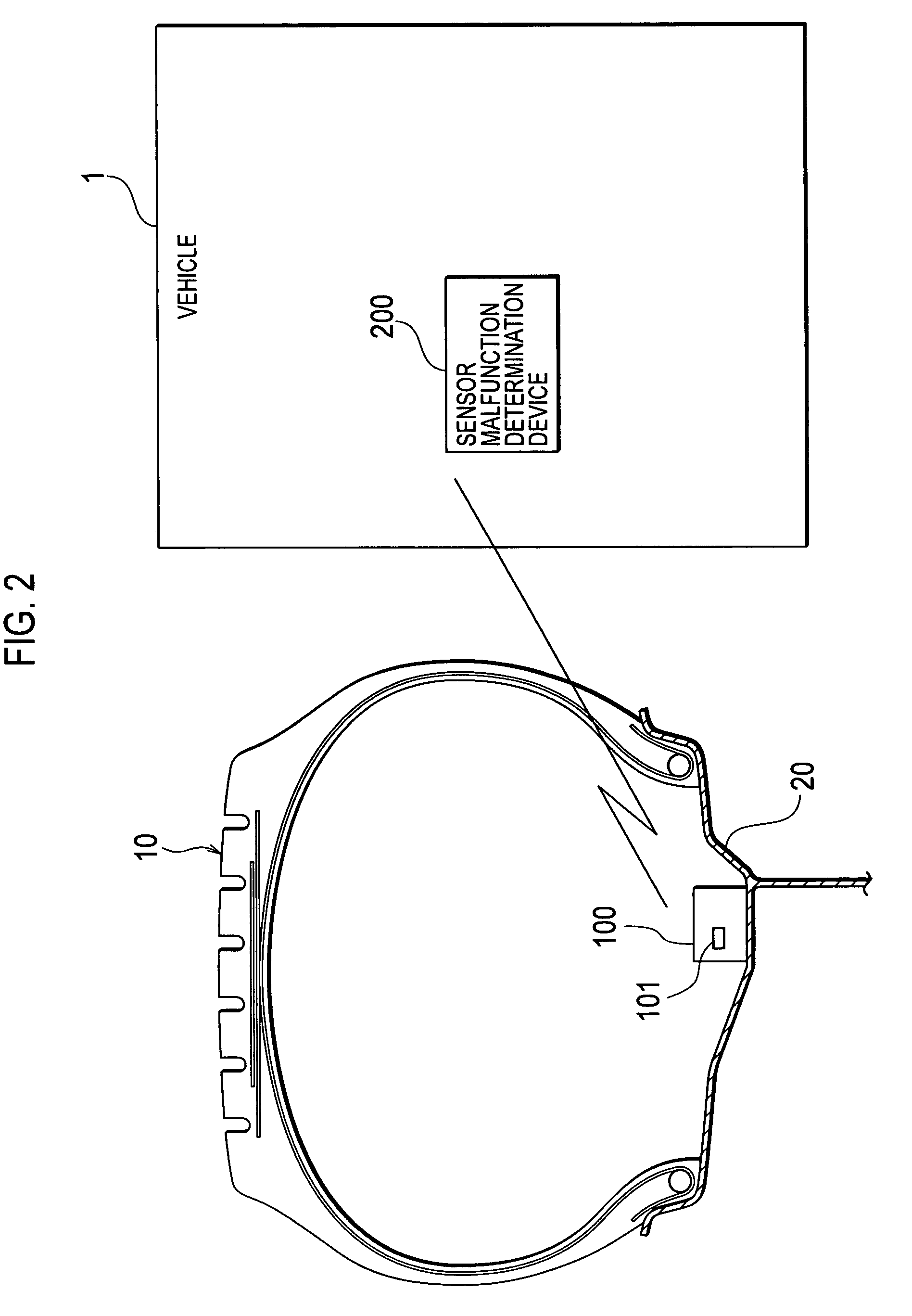
[0030]Next, with reference to FIG. 2 and FIG. 3, the configurations of the tire data transmission device 100 and a sensor malfunction determination device 200 will be described.
[0031]FIG. 2 is a cross-sectional view of the pneumatic tire 10 and the rim wheel 20 in the tread width direction. FIG. 2 also shows relations between the tire data transmission device 100 and the sensor malfunction determination device 200.
[0032]As shown in FIG. 2, a portion of a wheel drop o...
modified embodiment
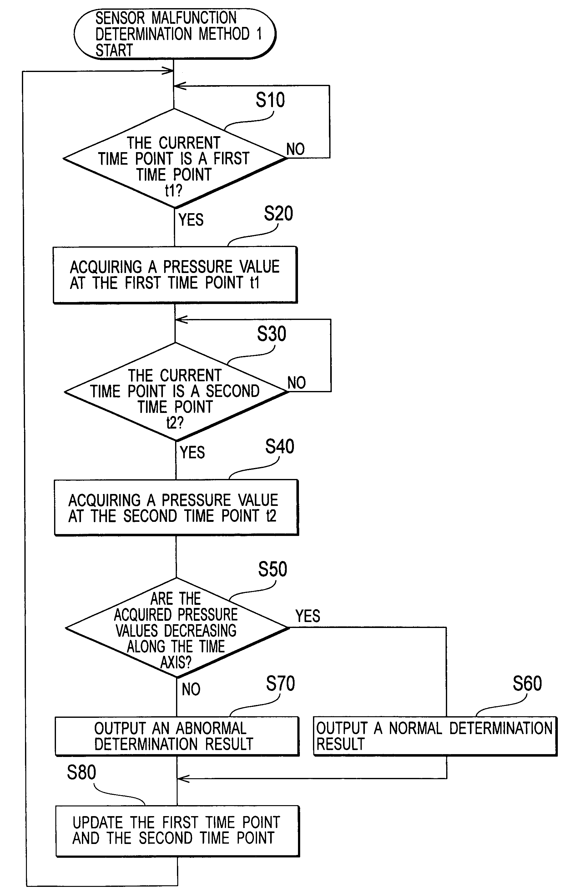
[0071]In this embodiment, although the sensor malfunction determination unit 207 uses two pressure values to determine whether or not the pressure sensor 101 is malfunctioning, it should be noted that the present invention is not limited to this case. Specifically, the sensor malfunction determination unit 207 may use three or more pressure values to determine whether or not the pressure sensor 101 is malfunctioning.
[0072]For example, the sensor malfunction determination unit 207 calculates an approximate expression by a least-square method using three or more pressure values along the time axis. When a value indicating the slope of the calculated approximate expression is the negative predetermined value or less, the sensor malfunction determination unit 207 determines the pressure sensor 101 is not malfunctioning.
[0073]According to this characteristic, the sensor malfunction determination unit 207 can calculate a more appropriate approximate expression by using three or more press...
second embodiment
[0074]In the first embodiment, when the acquired pressure values are decreasing along the time axis, the sensor malfunction determination unit 207 determines the pressure sensor 101 is not malfunctioning. However, when the pneumatic tire 10 is inflated, the sensor malfunction determination unit 207 is possible to determine erroneously whether or not the pressure sensor 101 is malfunctioning, as will be described below.
[0075]As shown in FIG. 6, for example, after the pneumatic tire 10 is inflated at t3 and the pressure value of the pneumatic tire becomes P4, the pressure value P4 gradually decreases along the time axis. In S20, the pressure value P5 at t4 is acquired, and then the pneumatic tire at t5 is inflated again. Thereafter, in S40, the pressure value P5 at t6 is acquired.
[0076]In this case, the pressure value P5 at t4 and the pressure value P5 at t6 are equal. Accordingly, even when the pressure sensor 101 is normally functioning, the sensor malfunction determination unit 207...
PUM
 Abstract
Description
Claims
Application Information
 - R&D
- Intellectual Property
- Life Sciences
- Materials
- Tech Scout
- Unparalleled Data Quality
- Higher Quality Content
- 60% Fewer Hallucinations
Browse by: Latest US Patents, China's latest patents, Technical Efficacy Thesaurus, Application Domain, Technology Topic, Popular Technical Reports.
© 2025 PatSnap. All rights reserved.Legal|Privacy policy|Modern Slavery Act Transparency Statement|Sitemap|About US| Contact US: help@patsnap.com


