Light source module
- Summary
- Abstract
- Description
- Claims
- Application Information
AI Technical Summary
Benefits of technology
Problems solved by technology
Method used
Image
Examples
embodiment 1
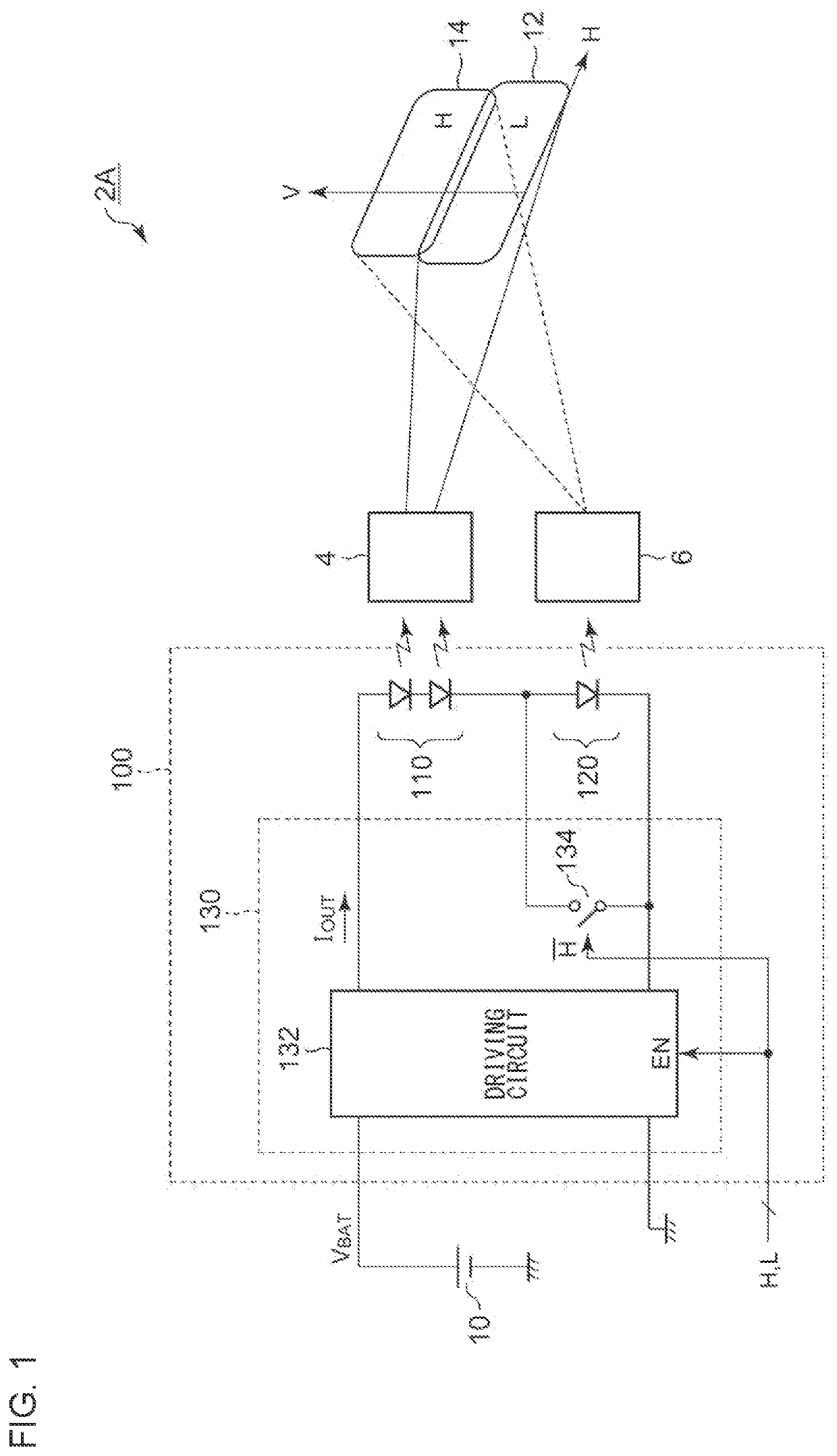
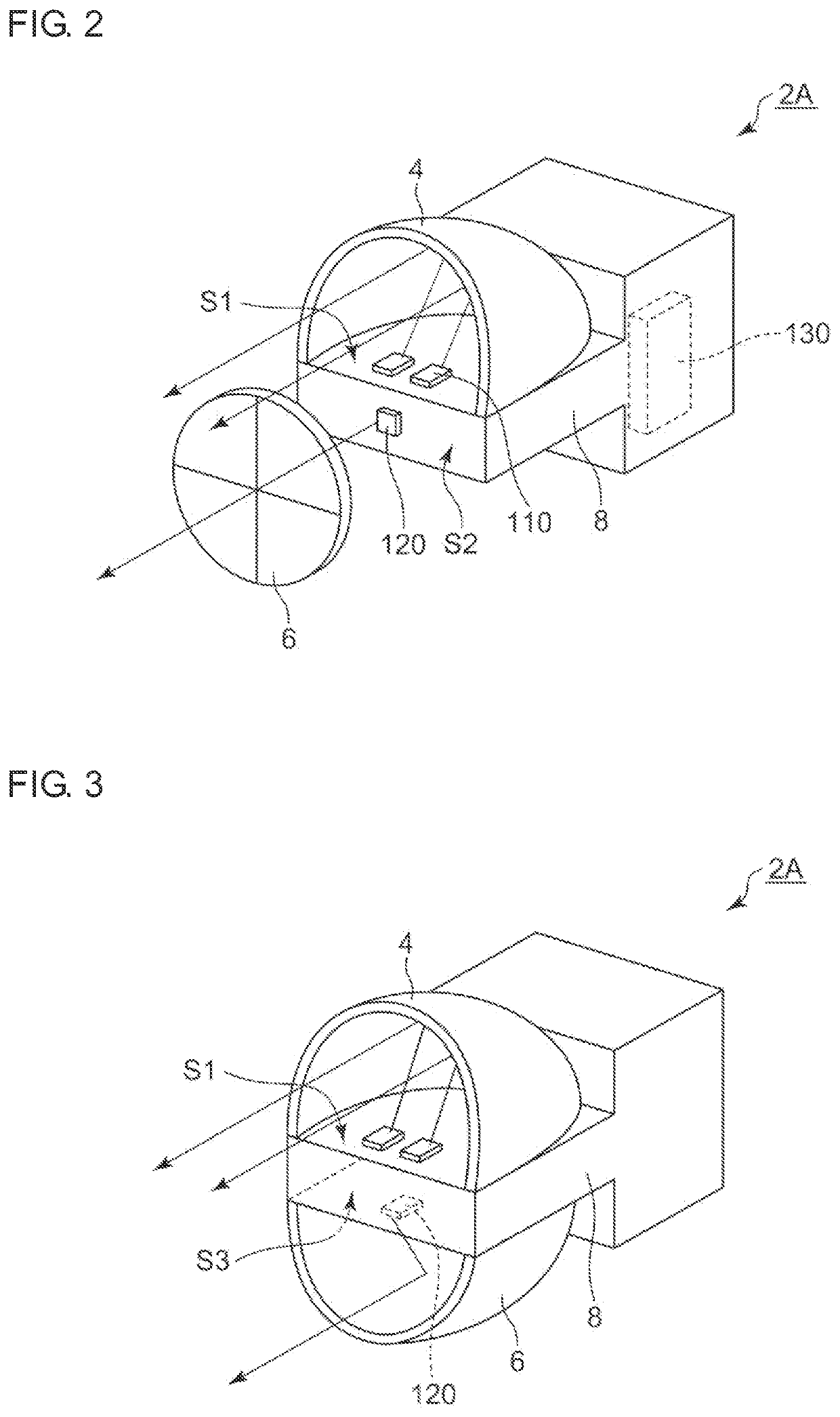
[0058]FIG. 1 is a diagram showing a headlamp 2A provided with a light source module 100 according to an embodiment 1. The headlamp 2A is mounted on a motorcycle and is capable of switching between a high beam and a low beam. The headlamp 2A includes a light source module 100, a first optical system 4, and a second optical system 6.
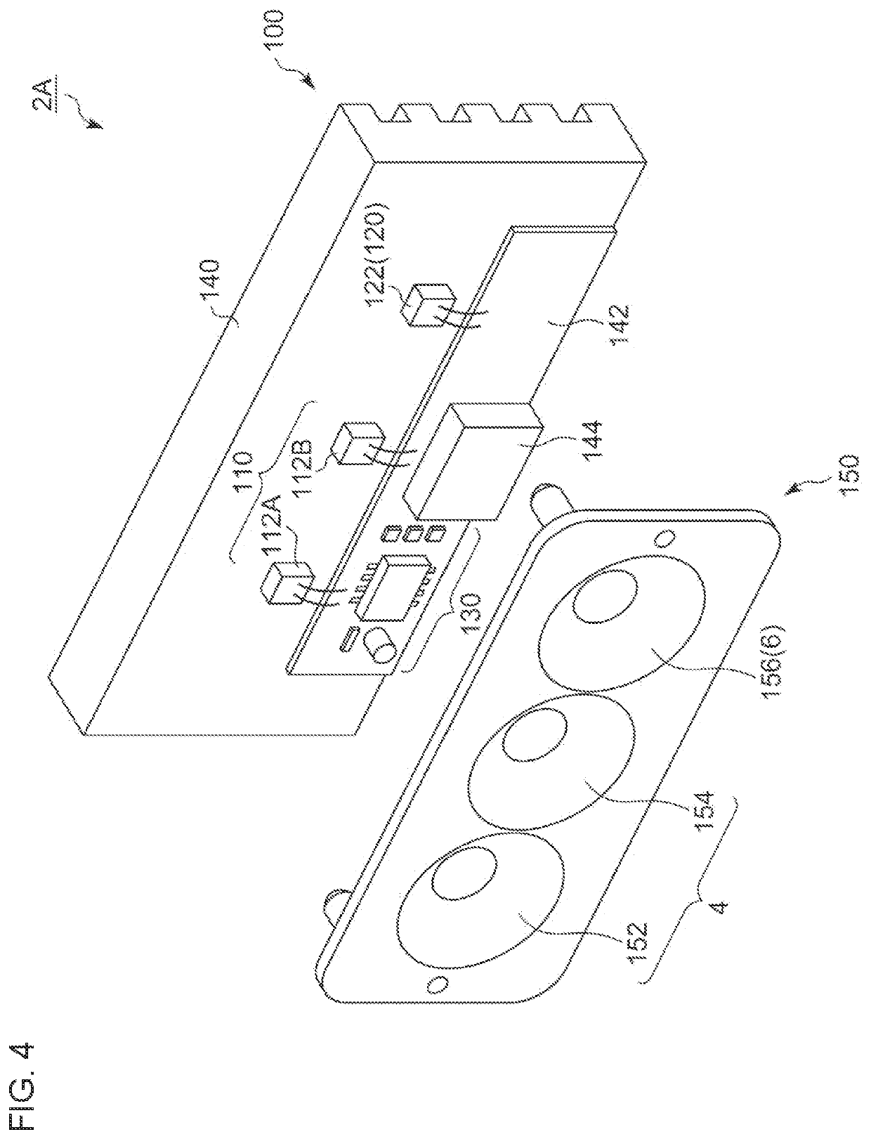
[0059]The light source module 100 includes a first light source 110, a second light source 120, a lighting circuit 130, and an unshown heatsink in the form of a module. The first light source 110 is arranged such that its output light is irradiated to a low-beam region 12 on a virtual vertical screen by means of the first optical system 4. The second light source 120 is arranged such that its output light is irradiated to a high-beam region 14 by means of the second optical system 6. The first light source 110 and the second light source 120 each include at least one semiconductor light-emitting element, examples of which include a light-emitting diode (LE...
embodiment 2
[0080]Description has been made in the embodiment 1 regarding an arrangement in which the driving current IOUT generated by the driving circuit 132 is constant regardless of the lighting mode (low-beam mode or high-beam mode) of the headlamp 2A. For this reason, power consumption, i.e., heat generation, in the high-beam mode becomes larger than that in the low-beam mode. Specifically, in a case in which the first light source 110 includes two LED chips and the second light source 110 includes a single LED chip as shown in FIG. 1, the heat generated in the high-beam mode is 1.5 times the heat generated in the low-beam mode. In some cases, this requires a heatsink to be formed with a larger size.
[0081]FIG. 6 is a diagram showing a headlamp 2C provided with a light source module 100C according to an embodiment 2. Description will be made regarding the configuration of the light source module 100C directing attention to the points of difference from the light source module 100 according...
embodiment 3
[0111]FIG. 14 is a diagram showing a headlamp 2B provided with a light source module 200 according to an embodiment 3. As in the embodiment 1, the headlamp 2B is mounted on a motorcycle, and is switchable between the high beam and the low beam. The headlamp 2B includes the light source module 200, the first optical system 4, the second optical system 6, and an unshown heatsink.
[0112]The light source module 200 includes a first light source 210, a second light source 220, a third light source 230, and a lighting circuit 240, in the form of a module. The first light source 210 and the third light source 230 are arranged such that the output light of each light source is irradiated by the first optical system 4 to the low-beam region 12 on a virtual vertical screen. The second light source 220 is arranged such that its output light is irradiated to the high-beam region 14 by the second optical system 6.
[0113]The first light source 210, the second light source 220, and the third light s...
PUM
 Abstract
Description
Claims
Application Information
 - R&D
- Intellectual Property
- Life Sciences
- Materials
- Tech Scout
- Unparalleled Data Quality
- Higher Quality Content
- 60% Fewer Hallucinations
Browse by: Latest US Patents, China's latest patents, Technical Efficacy Thesaurus, Application Domain, Technology Topic, Popular Technical Reports.
© 2025 PatSnap. All rights reserved.Legal|Privacy policy|Modern Slavery Act Transparency Statement|Sitemap|About US| Contact US: help@patsnap.com


