
Valve malfunctioning detection system for a vacuum sewer an associated methods

a vacuum sewer and malfunction detection technology, applied in the direction of sewage draining, programme control, instruments, etc., can solve the problems of reducing the performance degradation of the suction able to be applied, and the efficiency of the vacuum sewer system as a whole, so as to facilitate the detection of a malfunction in enhance and improve the efficiency of the vacuum sewer system.

Active Publication Date: 2012-07-24
DATA FLOW SYST
View PDF8 Cites 0 Cited by
  • Summary
  • Abstract
  • Description
  • Claims
  • Application Information

AI Technical Summary

Benefits of technology

"The present invention provides a system for detecting malfunctions in a vacuum sewer system. The system includes a radio unit placed in the vacuum pit, a gateway radio, a hub radio, and a server. The radio unit can detect the status of the vacuum sewer valve by using sensors such as acoustic, pressure, airflow, or valve position sensors. The system can also identify which type of sensor is used to detect the malfunction. By detecting malfunctions in a vacuum sewer system, the system can improve efficiency and decrease maintenance costs."

Problems solved by technology

One problem that arises in typical vacuum sewer systems, however, is the case where there is a malfunction in the valve connecting the suction pipe to the vacuum pit, i.e., the vacuum sewer valve.
A vacuum sewer valve that is stuck in an opened position, for example, may cause a decrease in efficiency of the vacuum sewer system.
A vacuum sewer valve that is stuck open on one vacuum pit, or even partially opened, may cause performance degradation of the suction able to be applied to the remaining pits, thereby decreasing the efficiency of the vacuum sewer system as a whole.
Decreased efficiency of such a system may lead to increased energy consumption.
Accordingly, if one vacuum sewer valve on one vacuum pit malfunctions, there currently exists no efficient manner to pinpoint the location of the vacuum pit where the valve may be malfunctioning.
This manual method, however, requires the use of many man hours, as well as the consumption of fuel to power the vehicle that is to transport the maintenance crew.

Method used


Image

  • Valve malfunctioning detection system for a vacuum sewer an associated methods
  • Valve malfunctioning detection system for a vacuum sewer an associated methods
  • Valve malfunctioning detection system for a vacuum sewer an associated methods

Examples


Embodiment Construction

[0020]The present invention will now be described more fully hereinafter with reference to the accompanying drawings, in which preferred embodiments of the invention are shown. This invention may, however, be embodied in many different forms and should not be construed as limited to the embodiments set forth herein. Rather, these embodiments are provided so that this disclosure will be thorough and complete, and will fully convey the scope of the invention to those skilled in the art. Like numbers refer to like elements throughout, and prime and multiple prime notations refer to similar elements in alternate embodiments.

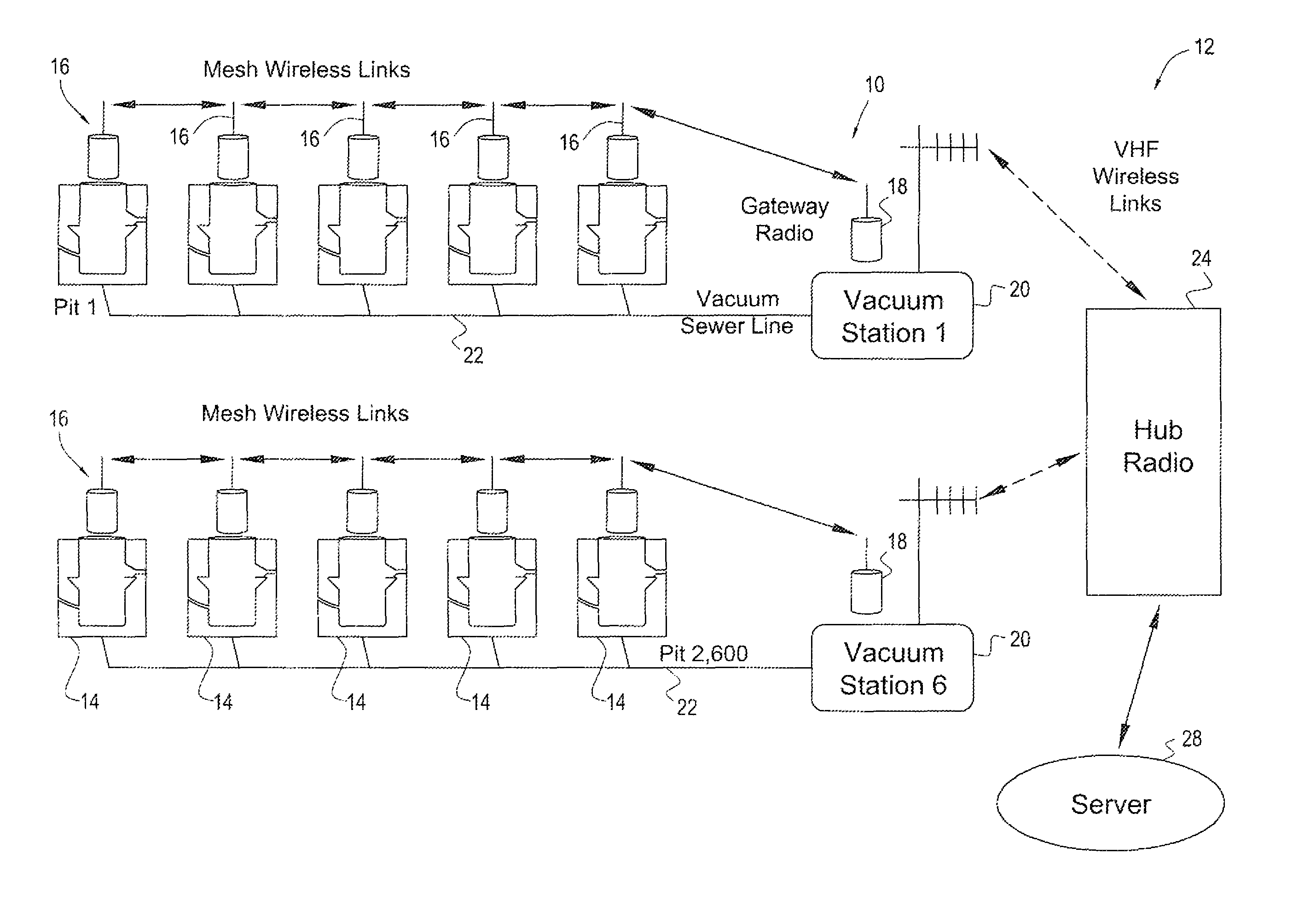
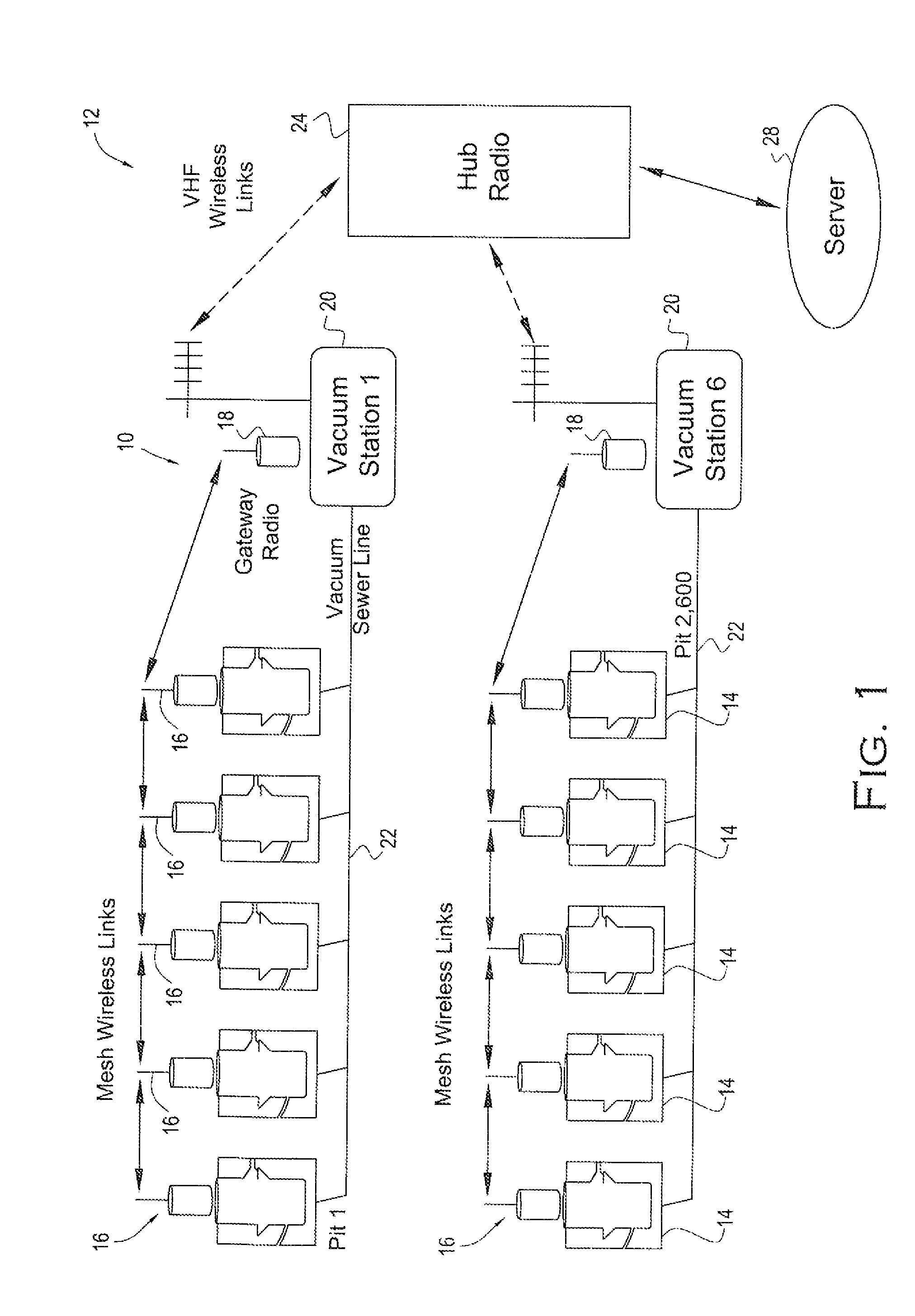
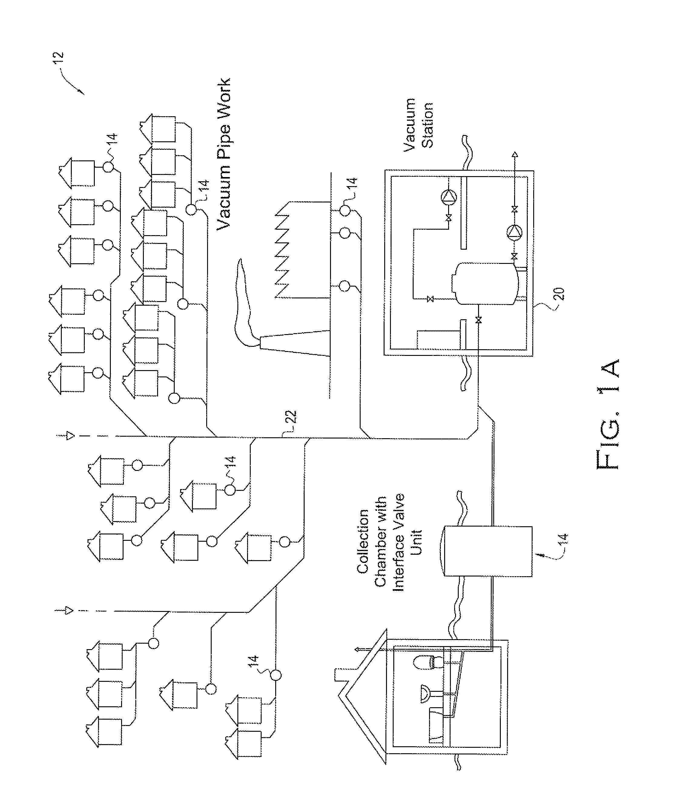
[0021]Referring initially to FIG. 1, a valve malfunctioning detection system 10 according to an embodiment of the present invention is now described in greater detail. As illustrated in FIG. 1, the valve malfunctioning detection system is adapted to be used in connection with a vacuum sewer system 12. A typical vacuum sewer system is illustrated in FIG. 1A. The vacuu...


PUM


Abstract

A valve malfunctioning detection system for use in a vacuum sewer system including a vacuum pit in fluid communication with a vacuum station is provided. The vacuum pit includes a vacuum sewer valve that is moveable between an opened position and a closed position. The valve malfunctioning detection system may include a radio unit adapted to be carried by the vacuum pit, a gateway radio in communication with the radio unit, a hub radio in communication with the gateway radio to receive a signal transmitted by the gateway radio, and a server in communication with the hub radio. The signal transmitted by the radio unit may include an indication of a status of the vacuum sewer valve.

Description

RELATED APPLICATIONS[0001]This application claims the benefit of U.S. Provisional Patent Application Ser. No. 61 / 307,651 titled VALVE MALFUNCTIONING DETECTION SYSTEM FOR A VACUUM SEWER AND ASSOCIATED METHODS filed on Feb. 24, 2010, the entire contents of which are incorporated herein by reference.FIELD OF THE INVENTION[0002]The present invention relates to field of vacuum sewer systems and, more specifically, to the field of detection of faulty valves in vacuum sewer systems and associated methods.BACKGROUND OF THE INVENTION[0003]Vacuum sewer systems are commonly used on large vessels, such as, for example, cruise ships. In recent times, vacuum sewer systems have been used for municipal sewer systems. As illustrated, for example, in U.S. Pat. No. 5,588,458 to Ushitora et al., a typical sewer system includes a vacuum pit, or a soiled water basin, that collects soiled water from a plurality of sources, e.g., in a residential setting, one soiled water basin may be used to accept soiled...

Claims


Application Information

Patent Timeline
Patent Type & Authority Patents(United States)
IPC IPC(8): G08B1/08
CPCE03F1/006E03F1/007E03F7/00G05B19/0428F16K37/0091F16K37/0083G05B2219/24048G05B2219/25187G05B2219/2642
Inventor SMAIDRIS, THOMAS F.SAUNDERS, R. BRENTGERHARDT, EDWARD C.
Owner DATA FLOW SYST
Learn More