
Image forming apparatus

a technology of image forming apparatus and forming sheet, which is applied in the direction of electrographic process apparatus, instruments, optics, etc., can solve the problems of paper sheet debris generated, high adhesion force, erratic sheet feeding, etc., and achieve the effect of preventing paper jams, accumulation, and sufficient dehumidification of recording sheets for printing

Active Publication Date: 2010-03-02
KONICA MINOLTA BUSINESS TECH INC
View PDF6 Cites 0 Cited by
  • Summary
  • Abstract
  • Description
  • Claims
  • Application Information

AI Technical Summary

Benefits of technology

[0007]The present invention has been achieved to overcome the above problems, and an object of the present invention is to provide an image forming apparatus which effectively prevents paper jams, accumulation of sheet debris on the conveyance path, and insufficiently fixed images due to fixing failure, while supplying sufficiently dehumidified recording sheets for printing.

Problems solved by technology

Accordingly, adhesion force tends to be high between the stacked sheets, and a top coated sheet is not easily separated from a second stacked coated sheet on the tray, whereby the coated sheets are not easily supplied to the apparatus, resulting in erratic sheet feeding.
Still further, when the recording sheet is conveyed under said high humidity, and printing is conducted on the sheet, paper sheet debris generated from the recording sheets accumulates in the conveyance path, interfering with proper operation of optical sensors mounted in the conveyance path to detect the recording sheets.
However, such dehumidification is not sufficient in some cases.
For example, just after power is switched on, or during environmental variation, if coated sheets are being conveyed in the path, they tend to cause a jam, or sheet debris may accumulate on the conveyance path, which are major problems.
Further, if printing is conducted on the recording sheet under high humidity, heat is absorbed by moisture in the recording sheet, and fixing temperature in the recording sheet does not reach a desired temperature, which may cause an insufficiently fixed image due to low fixing temperature.
Still further, in the image forming apparatus proposed in the above patent document, sheet debris tends to accumulate on the optical sensor mounted near the tray which supplied the sheets, tending to cause the coated sheets to jam, due to the high humidity environment.

Method used


Image

  • Image forming apparatus
  • Image forming apparatus
  • Image forming apparatus

Examples


embodiment 1

[0082 see FIG. 8

[0083]In the tray which supplies the sheets for image formation, when the humidity inside the tray is equal to or lower than the predetermined value, the control to conduct printing is explained while referring to FIG. 8.

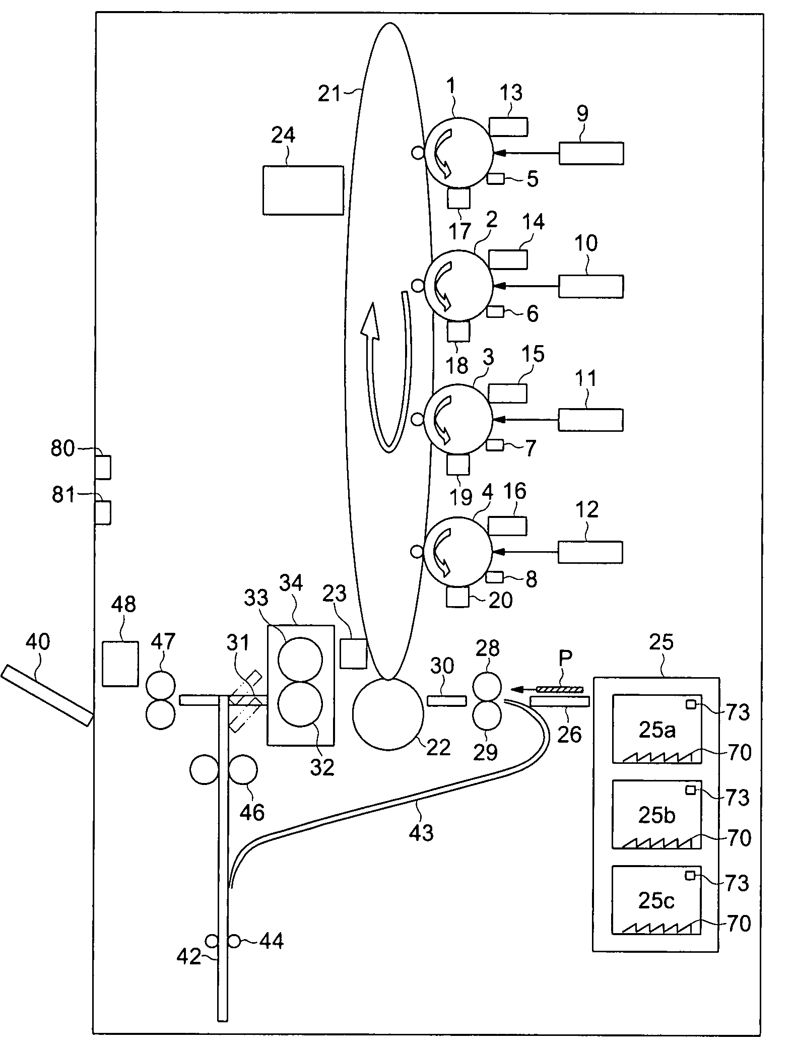
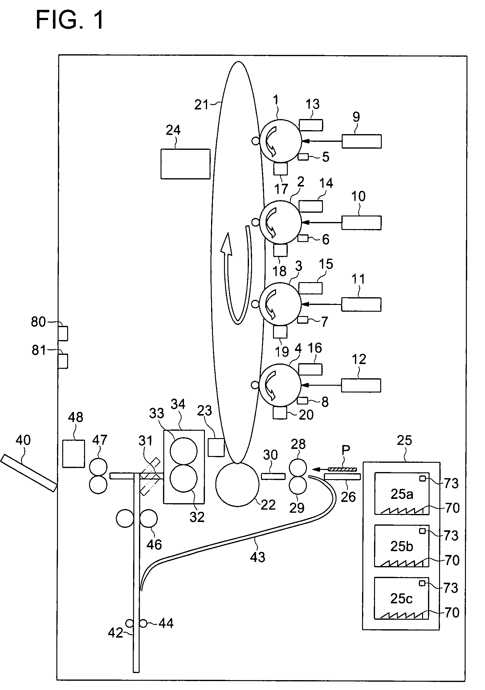
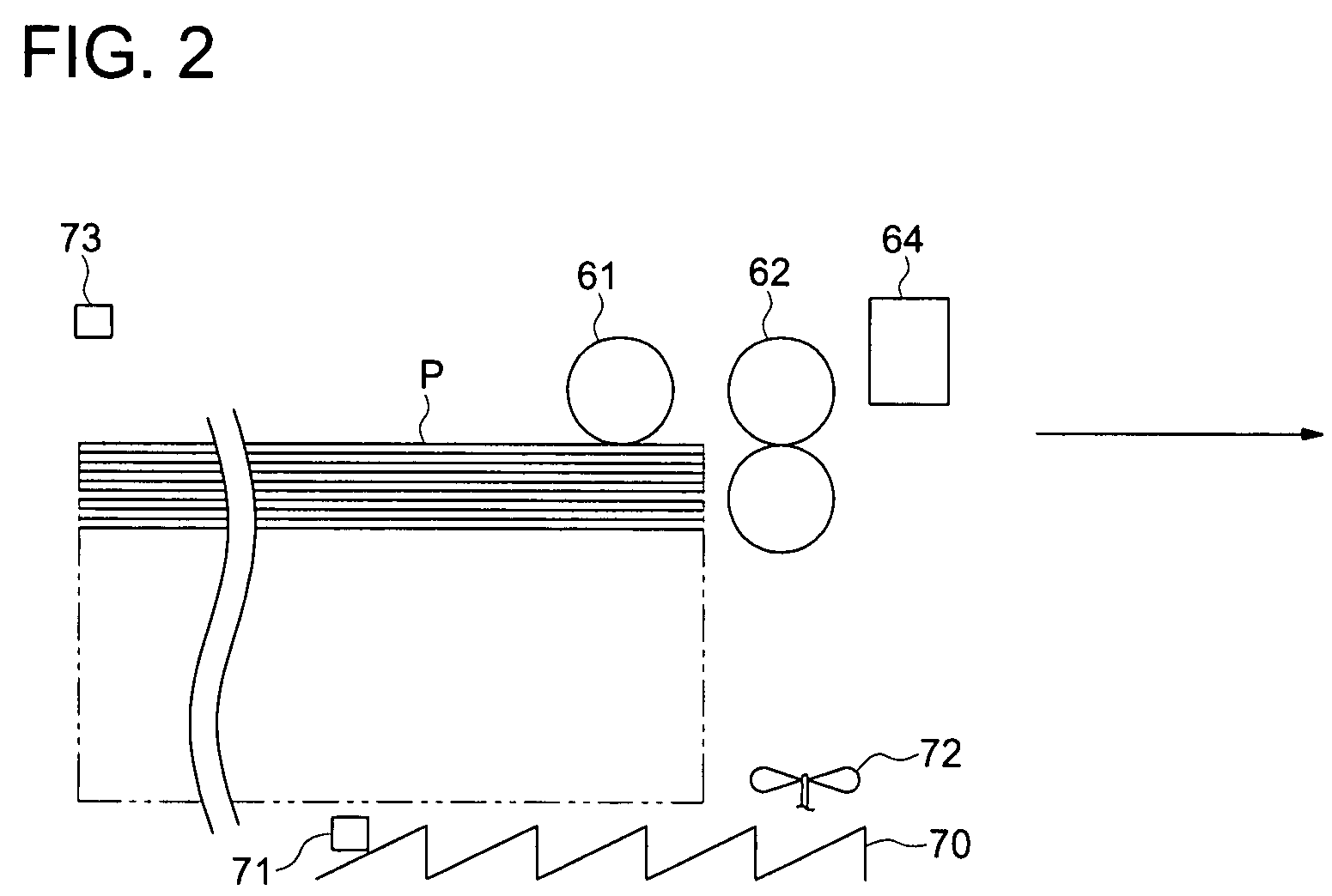
[0084]Control section 103 awaits printing instructions, such as pressing signal of the copy button on operation section 120 (step a1), and when the printing instruction is entered, control section 103 judges the humidity inside the tray which is to supply the sheets (step a2). Specifically, the humidity and the temperature are detected by external humidity sensor 80, external temperature sensor 81 and tray temperature sensor 73, and the detected results are sent to control section 103. Based on the detected results, control section 103 calculates a target temperature inside the tray to be attained inside the tray as the predetermined humidity value. If the temperature in the tray is higher than the targeted temperature, control section 103 judges tha...


PUM


Abstract

An image forming apparatus, including an image forming section which conducts image formation on a sheet based on an image data, a tray which accommodates the sheets to be supplied to the image forming section, a humidity detecting unit which detects humidity inside the tray, a dehumidifying device which conducts dehumidification inside the tray; and a control section which controls the image forming section to prohibit image formation when the humidity inside the tray is higher than a predetermined value, the control section further controls the dehumidifying device to conduct the dehumidification inside the tray when the humidity inside the tray is equal to or lower than the predetermined value, and the control section still further controls the image forming section to conduct the image formation on the when the humidity inside the tray has been equal to or lower than the predetermined value.

Description

[0001]This application is based on Japanese Patent Application Nos. JP2006-183789 filed on Jul. 3, 2006, and JP2007-124415 filed on May 9, 2007, with the Japanese Patent Office, the entire content of both are hereby incorporated by reference.TECHNICAL FIELD[0002]The present invention relates to an image forming apparatus, such as a copy machine, a printer, and a compound machine, and in particular, to an image forming apparatus in which humidity can be controlled.BACKGROUND OF THE INVENTION[0003]In an image forming apparatus, such as a copy machine, a printer, and a compound machine, based on image data which is read by a document reading device, a toner image is formed on an image carrier provided in the image forming apparatus, and after the toner image is transferred onto a recording sheet supplied from a tray, the toner image is fixed, whereby permanent image formation (or printing) is performed.[0004]Since various types of sheets are used for printing, a coated sheet is charact...

Claims


Application Information

Patent Timeline
Patent Type & Authority Patents(United States)
IPC IPC(8): G03G21/20
CPCG03G15/6502G03G21/203G03G2215/00776
Inventor TAKI, KENJISUZUKI, CHIKATSUAKIMOTO, FUSAKO
Owner KONICA MINOLTA BUSINESS TECH INC
Learn More