Gridlock processing method

a processing method and gridlock technology, applied in wave based measurement systems, instruments, reradiation, etc., can solve the problems of unnecessary launching of a large number of countermeasure missiles and the potential for missing the target of many of the countermeasures, and achieve the effect of improving the registration

Inactive Publication Date: 2010-03-02
LOCKHEED MARTIN CORP
View PDF2 Cites 7 Cited by
  • Summary
  • Abstract
  • Description
  • Claims
  • Application Information

AI Technical Summary

Benefits of technology

[0009]A method according to an aspect of the invention is for determining the orientation and location of a platform for purposes of gridlock and or registration. The platform carries at least a local sensor which tracks remote objects. The method comprises the step of generating from the local sensor first, second, third, and fourth local sensor signals representing at least first, second, third and fourth noncoplanar remote object positions, respectively. The method further includes the step of acquiring first, second, third, and fourth remote external signals representing the positions of the first, second, third, and fourth objects. Computations are performed by taking the difference between the first local sensor signal and the second local sensor signal, the third local sensor signal, and the fourth local sensor signal, to thereby generate a set of first, second, and third translationally invariant local pseudomeasurements. The difference is taken between the first remote external signal and the second remote external signal, the third remote external signal, and the fourth remote external signal, to thereby generate a set of first, second, and third translationally invariant remote pseudomeasurements. The first, second, and third local and remote pseudomeasurements are iteratively filtered to thereby generate an estimated rotation which results in the best agreement between the local and remote pseudomeasurements. This estimated rotation is used to at least partially correct the coordinate system associated with the local sensor, to thereby improve the registration between or among the first, second, third, and fourth local and remote sensor signals.

Problems solved by technology

If correlation is not performed, the possibility exists that each of several remote sensors will sense the same target, but, due to unavoidable inaccuracies among the coordinate systems of the various sensors or vehicles, at disparate locations.
It is easy to understand that this can be very disadvantageous, as a single hostile target sensed by many friendly forces might be incorrectly interpreted as being a swarm of hostiles, each at a slightly different location.
This, in turn, might lead to the unnecessary launching of a large number of countermeasure missiles, when there is but a single target.
In addition, since the target's actual location appears differently at each of the friendly vehicles, there is the potential for missing the target with many of the countermeasures.

Method used


Image

  • Gridlock processing method
  • Gridlock processing method
  • Gridlock processing method

Examples


Embodiment Construction

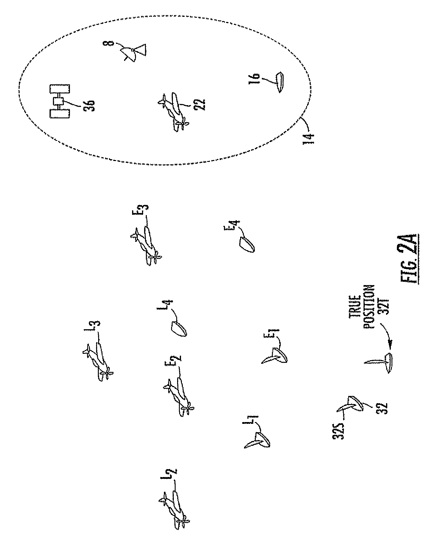
[0018]FIG. 2A is a representation of the targets perceived by local and remote sensors. More particularly, ship 32 of FIG. 2A senses targets using its own sensor(s) 32S. The true position of ship 32 in the coordinate system of flotilla 14 is indicated by 32T. As illustrated in FIG. 2A, four targets are sensed or detected by “ownship” or “local” sensor 32S. The first target is a surface vehicle or ship locally sensed at a location designated L1. The second target is an aircraft locally sensed at location L2. The third target is a second aircraft locally sensed at location L3. The fourth target is another surface vehicle locally sensed at location L4.

[0019]As mentioned, the various targets are sensed by sensors which are associated with other platforms than ownship 32. More particularly, land-based platform 8, ship 16, aircraft 22, and spacecraft 36 of FIG. 2A are fitted with their own sensors, which also detect the four targets. Any one of the sensors associated with the remote platf...


PUM


Abstract

Targets are sensed by a first sensor in a first coordinate system and by a second sensor in a second coordinate system. Gridlock or congruence between the coordinate systems is achieved by sensing at least four targets with both sensors. Pseudomeasurements are generated in both local and external coordinate systems by taking the differences between a first target location and each of second, third, and fourth target locations. The pseudomeasurements are filtered in corresponding pairs, to thereby generate an estimated rotation matrix between the local and external coordinate systems. The estimated rotation matrix is applied to the local coordinate system. The target locations in the rotated local and external coordinate systems are filtered in corresponding pairs to generate an estimated translation vector. The rotation and translation are applied to the local coordinate system to bring it into congruence with the external coordinate system.

Description

BACKGROUND OF THE INVENTION[0001]Military techniques often include the deployment of a plurality of platforms or vehicles, such as armored vehicles in a terrestrial context, aircraft in an aerial environment, and ships in a naval context. Many, if not most, of these vehicles are equipped with one or more sensors for sensing the environment of the vehicle and for producing signals indicative of the presence of potential targets. As to any particular vehicle, its sensors may respond to other friendly vehicles and also to potentially unfriendly vehicles and other targets. It should be noted that in some contexts an individual may carry sensors and for this purpose may be considered to be a platform or vehicle.[0002]The sensors of a group of vehicles (or vehicles and individuals) dispersed over a combat region will often gather more total information than any single vehicle alone, as the locations and capabilities of some of the sensors allows the sensed area to extend beyond the sensin...

Claims


Application Information

Patent Timeline
Patent Type & Authority Patents(United States)
IPC IPC(8): G06F19/00G06F15/00
CPCG01S5/0289G01S13/86G01S13/726
Inventor SCZANIECKI, LESZEK J.
Owner LOCKHEED MARTIN CORP
Why Eureka
Try Eureka