Vacuum broom apparatus

a vacuum cleaner and broom technology, applied in the field of vacuum cleaners, can solve the problems of ineffective dislodging action, inefficient dislodging of debris particles, and motor-driven roller brushes or beater bars intended for use on carpeted surfaces,

Inactive Publication Date: 2010-03-09
H & J
View PDF13 Cites 5 Cited by
  • Summary
  • Abstract
  • Description
  • Claims
  • Application Information

AI Technical Summary

Problems solved by technology

Vacuum cleaner heads that include motor-driven roller brushes or beater bars and intended for use on carpeted surfaces are generally not well suited for use on hard floor surfaces such as those of tile, concrete, stone or the like.
However, this dislodging action is problematic because it is confined to a region which peripherally encircles the suction inlet opening of the nozzle, and thus tends to not only inefficiently gather dislodged debris particles, but undesirably scatters a good percentage of the particles into the atmosphere.

Method used


Image

  • Vacuum broom apparatus
  • Vacuum broom apparatus
  • Vacuum broom apparatus

Examples


embodiment 50

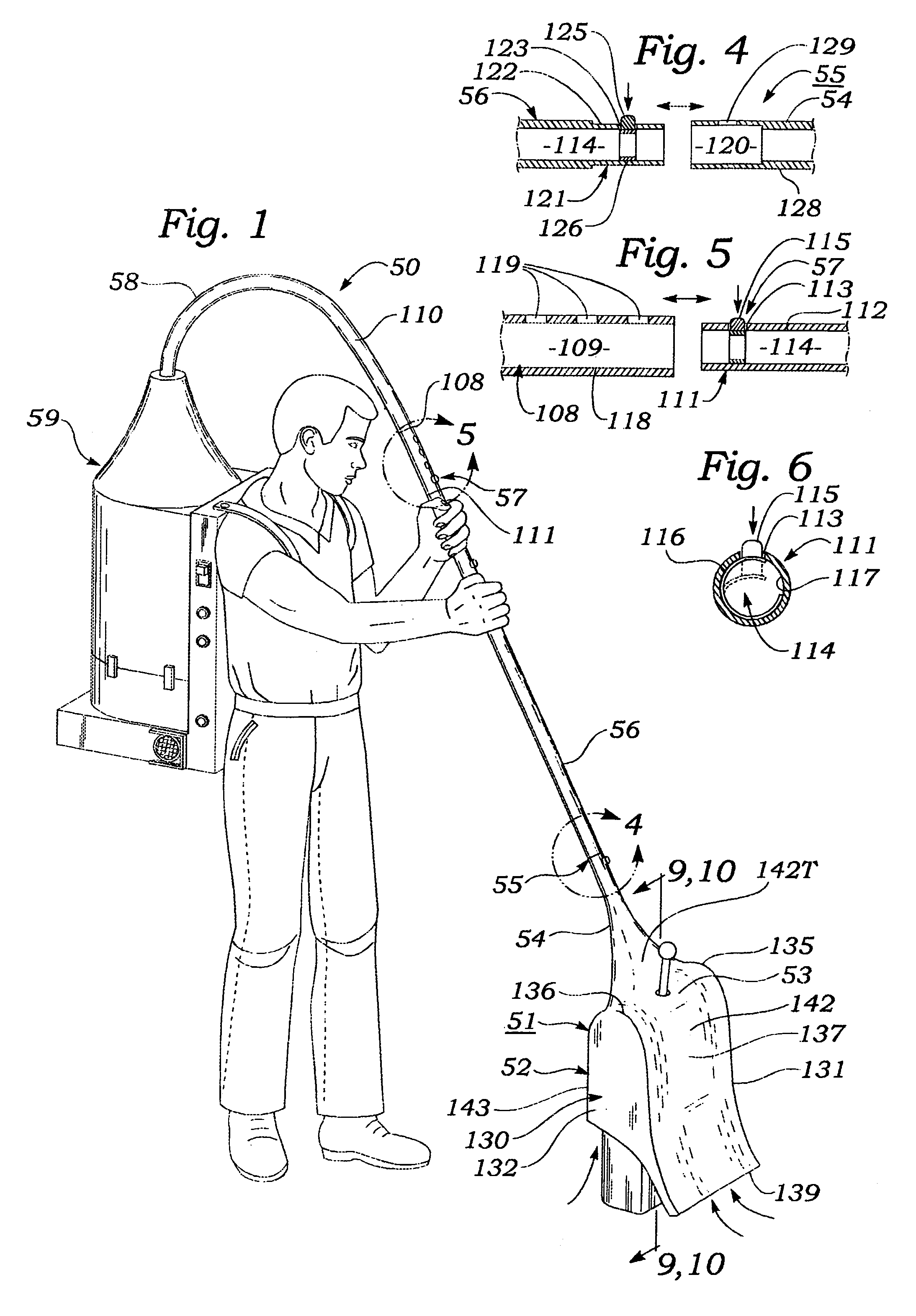
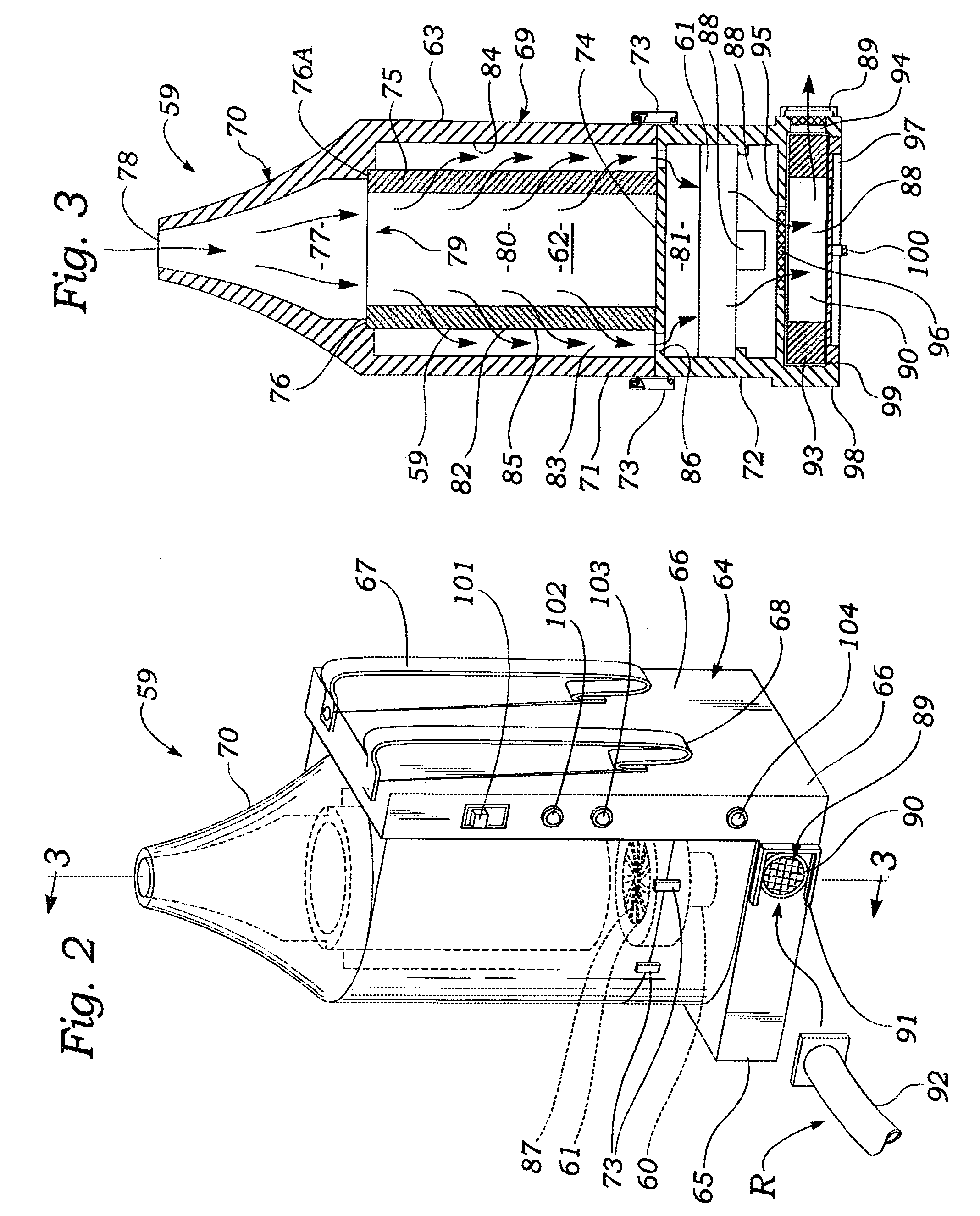
[0063]FIGS. 1-10 illustrate a basic embodiment 50 of a vacuum broom apparatus according to the present invention. As shown in FIG. 1, apparatus 50 includes a cleaner head 51 which includes a hollow body 52 that has protruding from an upper surface 53 thereof an upwardly and rearwardly angled vacuum inlet tube 54. Vacuum inlet tube 54 is connected by a releasable coupler 55 to the lower end of an elongated hollow tubular handle 56, the upper end of which is connected via a telescopically adjustable coupler 57 to a free end of a vacuum hose 58 which has a fixed end attached to a vacuum power unit 59. As shown in FIGS. 2 and 3 and as will be described in detail below, vacuum power unit 59 includes an electric motor 60 which rotates a fan 61 to produce a negative pressure or partial vacuum within the hollow interior space 62 of a housing 63 of the vacuum power unit, negative pressure being coupled through hose 58 and handle 56 to cleaner head 51.

[0064]Referring to FIGS. 18-23 in additio...

embodiment 51

[0073]The structure and function of a basic embodiment 51 of a cleaner head for use in the apparatus 50 shown in FIG. 1 may be best understood by referring to FIGS. 7-10 in addition to FIG. 1.

[0074]As shown in FIGS. 1, 7 and 8, body 52 of cleaner head 51 includes a hollow box-like enclosure or housing 130 which has generally flat, parallel, vertically disposed left and right side wall panels 131, 132. As shown in FIG. 1, left and right side wall panels 131, 132 each has a lower portion 133, 134, respectively, which has a shape approximating that of a vertically elongated rectangle, modified by a convex, arcuately curved upper edge wall 135, 136, respectively. Housing 130 also has a front wall panel 137 which is disposed transversely to left and right side wall panels 131, 132. Front panel 137 has the shape approximating that of a sinuously curved vertically elongated rectangular plate which is relatively longer than left and right side wall panels 131, 132. Front wall panel 137 has ...

third embodiment

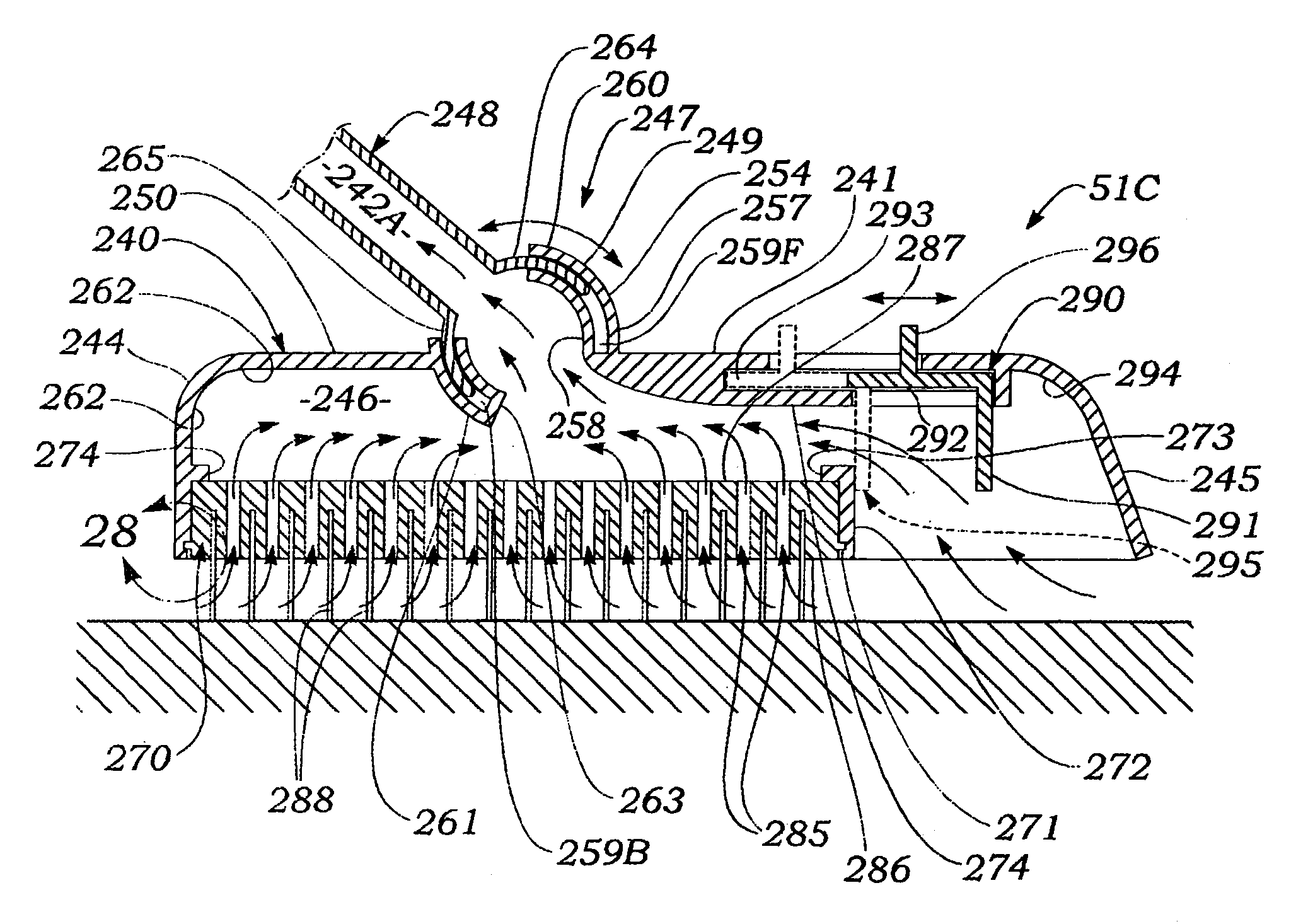
[0086]FIGS. 25-32 illustrate a vacuum broom cleaner head 51C for use within vacuum broom apparatus 50 of FIG. 10.

[0087]As shown in FIGS. 25-29, vacuum cleaner head 51 includes a housing 240 which has the shape of a short, generally rectangularly-shaped box which includes a generally flat, rectangularly-shaped upper wall panel 241 that has protruding perpendicularly downwardly therefrom left and right flange walls 242, 243 which have a generally rectangular shape elongated in a fore-and-aft direction. Housing 240 also has a rear flange wall 244 which has a laterally elongated, generally rectangular shape and which protrudes generally perpendicularly downwards from a rear edge of upper wall panel 240. Housing 240 also has a front generally rectangularly-shaped, laterally elongated wall panel 245 which angles forward obliquely from a front edge of upper wall panel 241.

[0088]As shown in FIG. 26, housing 240 of cleaner head 51C a hollow interior space 246 which has a shape approximating ...


PUM


Abstract

A vacuum broom apparatus for removing particulate debris from surfaces such as those of floors includes a housing which has an upper wall from which protrudes a vacuum inlet tube connectable to a vacuum power source. The housing includes a shroud which protrudes downwardly from the upper wall and peripherally surrounds a broom which protrudes downwardly within the shroud through a bottom opening thereof. One or more vacuum nozzles which communicate with the vacuum inlet tube are positioned adjacent to the broom. Optionally, a front wall of the shroud is elastically flexible to thereby effect an air dam between a lower edge of the front wall and a floor surface against which it may be pressed. Also, the broom may take the form of a block which at least partly encloses a lower entrance opening of the shroud, the block having a lower surface from which bristles protrude downwardly, and a plurality of vacuum passageways interspersed within the bristles and which have lower debris entrance openings in the lower surface of the block, and upper debris exit openings through an upper surface of the block which communicates with a negative pressure region of an interior region of the shroud.

Description

[0001]This is a Continuation-In-Part application of Ser. No. 10 / 315,956, filed on Dec. 10, 2002, now abandoned.BACKGROUND OF THE INVENTION[0002]A. Field of the Invention[0003]The present invention relates to devices and apparatus for removing dust and dirt from floors. More particularly, the invention relates to a vacuum broom apparatus which utilizes a synergistic combination of sweeping and vacuuming functions to efficiently remove dirt and dust from floor surfaces while minimizing undesired dispersal of errant dust or dirt particles into the atmosphere.[0004]B. Description of Background Art[0005]Periodic removal of dust, dirt and other debris which accumulates on floors of buildings is performed using a limited variety of well known methods. Thus concrete floors of small industrial or commercial buildings are sometimes washed or hosed down but more typically swept with hand-operated push brooms. Floors of larger buildings are sometimes cleaned using motor-driven rotating brushes ...

Claims


Application Information

Patent Timeline
Patent Type & Authority Patents(United States)
IPC IPC(8): A47L9/06
CPCA47L5/36A47L9/06A47L9/066
Inventor SHAHBAZ, JAMSHID JIM
Owner H & J
Why Eureka
Try Eureka