
Line block

a line block and corner wall technology, applied in the field of line blocks, can solve the problems of inefficiency of known methods for building quoin corner wall structures, and achieve the effect of convenient movemen

Inactive Publication Date: 2010-03-09
HUDSON ROBERT E
View PDF16 Cites 14 Cited by
  • Summary
  • Abstract
  • Description
  • Claims
  • Application Information

AI Technical Summary

Benefits of technology

[0009]Thus, the present invention is directed to a line block to aid in the proper and efficient construction of brick walls, including brick walls having quoin corners. In various exemplary, nonlimiting embodiments of the present invention, the line block comprises a line block body having a first leg and a second leg extending therefrom to form a substantially U-shaped line block. A corner pole receiving groove is defined by the line block body, the first leg, the second leg.
[0011]In various exemplary, nonlimiting embodiments, the line block also includes a line extension leg having an extension leg line groove formed therein. The inclusion of the extension leg and line groove allows the line to be positioned relative the line block so as to allow easier manipulation of the line around the line block.
[0014]When the quoin portion of the wall has been built, the line blocks are moved upward along the corner poles and the line can again be easily moved from the quoin line grooves to the wall line grooves, so that the standard wall portions can be built.

Problems solved by technology

Unfortunately, when quoin corners are constructed, the positioning of the corner poles must be changed so that a straight reference line can be provided for setting the quoin corner blocks.
Because of the difficulty this creates, it is common for the blocks that make up the quoin corner to be set without a straight reference line.
The known methods for constructing quoin corner wall structures are inefficient and can produce inconsistent results.

Method used


Image

  • Line block
  • Line block
  • Line block

Examples


Embodiment Construction

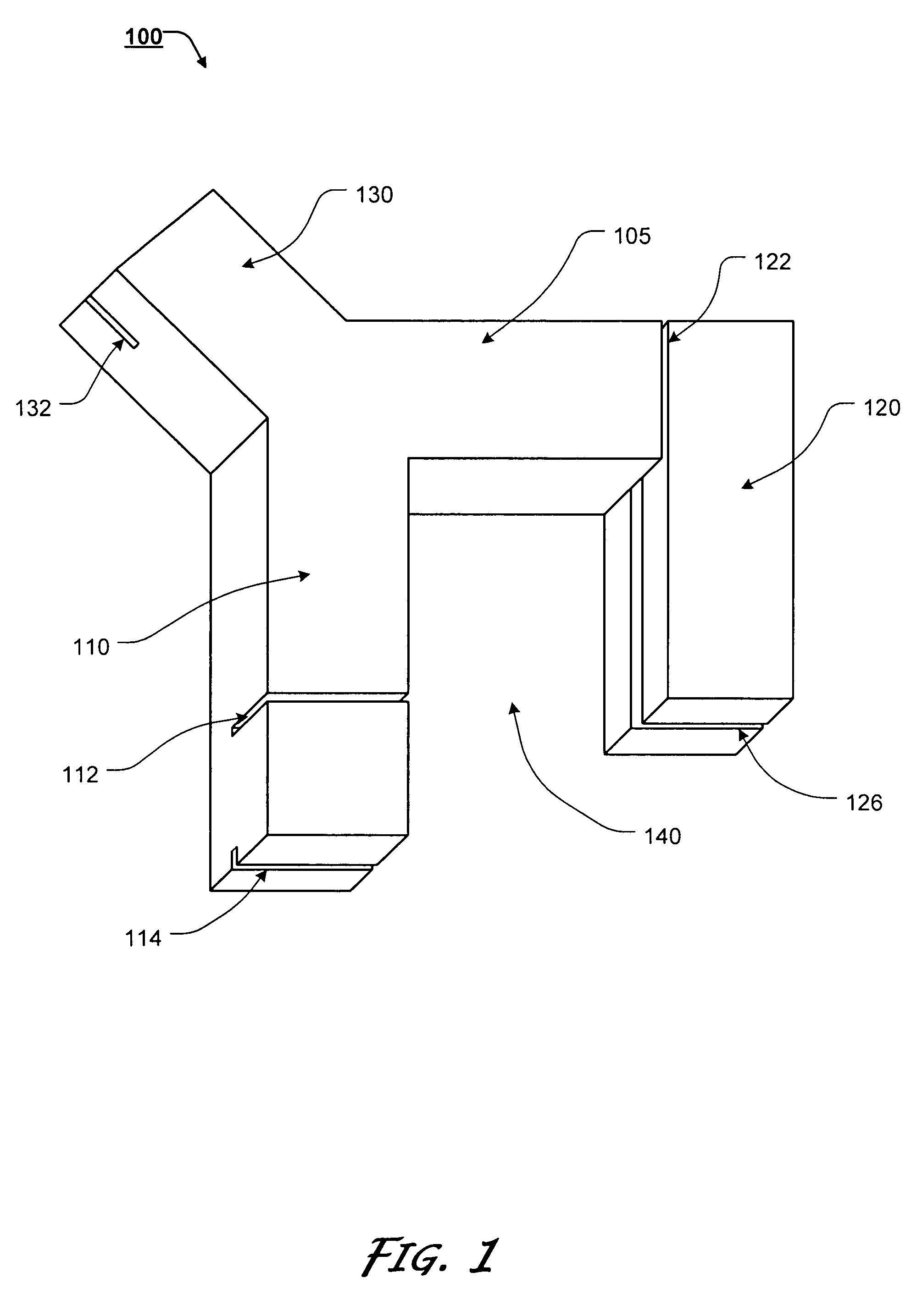
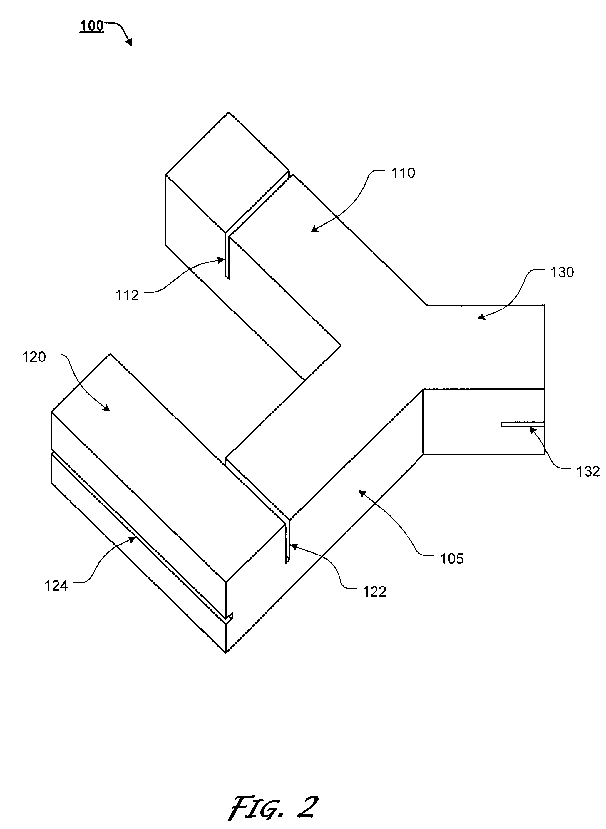
[0035]For simplicity and clarification, the design factors and operating principles of the line block of this invention are explained with reference to various exemplary embodiments of a line block according to this invention. The basic explanation of the design factors and operating principles of the line block is applicable for the understanding, design, and use of the line block of this invention.

[0036]It should be appreciated that the terms “line block”, “wall line”, and “quoin line” are used for basic explanation and understanding of the systems, methods, and / or apparatuses of this invention. Therefore, the terms “line block”, “wall line”, and “quoin line” are not to be construed as limiting the systems, methods, and apparatuses of this invention.

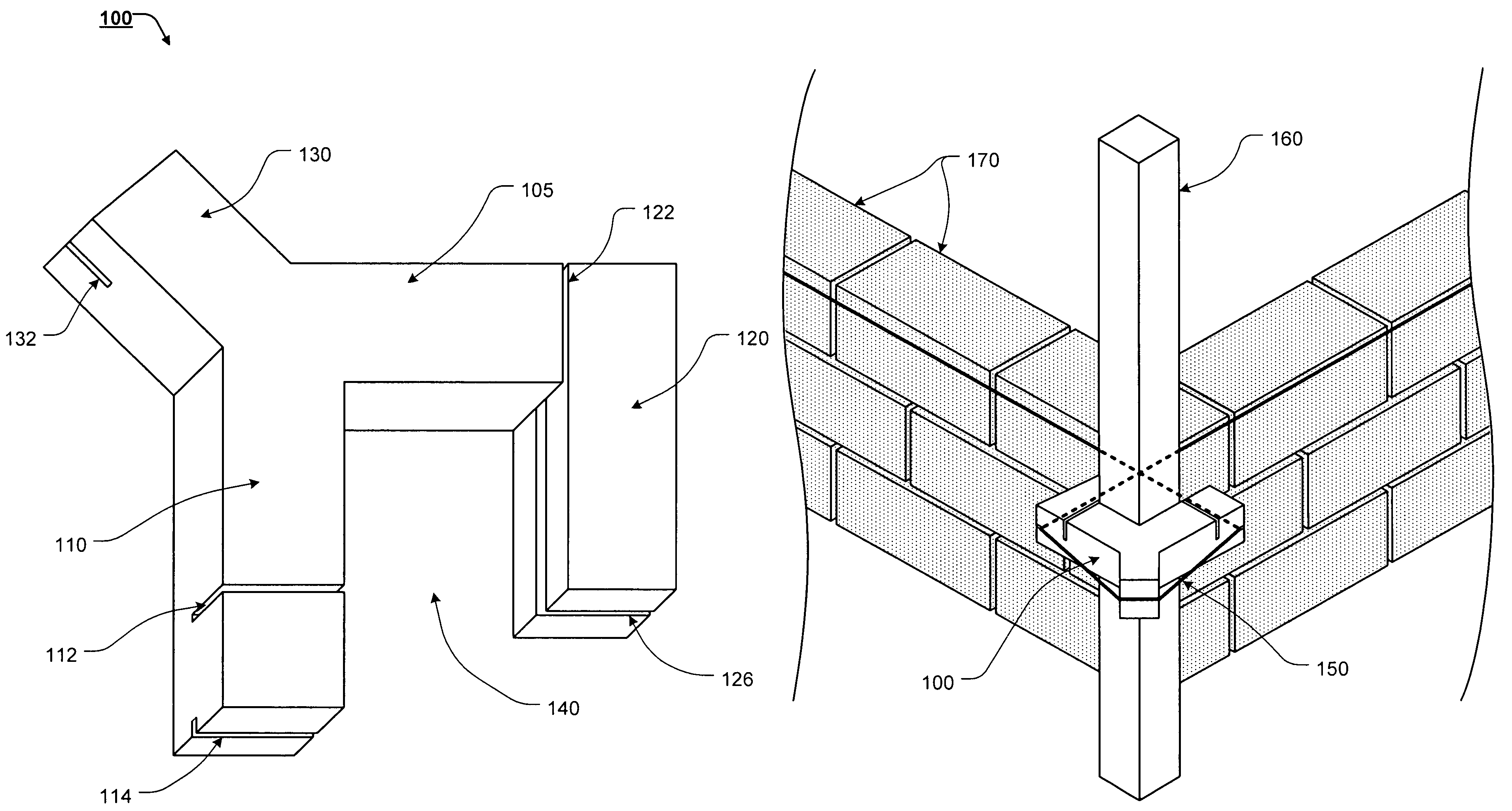
[0037]It should also be appreciated that while the various exemplary embodiments of the present invention are primarily described and shown as being used to construct brick wall structures they should not be construed as limiting the u...


PUM


Abstract

A line block having a body; a first leg extending substantially perpendicular to a longitudinal axis of the body; a first leg quoin line groove extending from a front surface of the first leg; a first leg wall line groove extending from a bottom surface of the first leg; a second leg spaced apart from the first leg, wherein the second leg extends substantially perpendicular to a longitudinal axis of the body, wherein a corner pole receiving groove is defined between at least a portion of the body, the first leg, and the second leg; a second leg quoin line groove extending from a front surface of the body and a front surface of the second leg, along a portion of an inner wall surface of the second leg; and a second leg wall line groove extending from a right side surface of the second leg.

Description

BACKGROUND OF THE INVENTION[0001]1. Field of the Invention[0002]This invention relates generally to line blocks. In particular, the present invention relates to a line block to aid in the proper and efficient construction of brick walls, including brick walls having quoin corners.[0003]2. Description of Related Art[0004]When brick, block, or stone structures are built, it is important that any walls that form the structure are straight and level. Typically, once the framing of a wall has been completed and the brick is to be laid, corner poles are placed proximate the outside edges were the wall will be constructed and a string, or line, is stretched between any two corner poles to provide a straight reference line to which the wall can be built.[0005]The line is initially placed proximate a respective ground level so that an initial line of bricks can be laid. As the wall is built upward, the line can be moved upward on the corner poles so as to provide a straight reference line fo...

Claims


Application Information

Patent Timeline
Patent Type & Authority Patents(United States)
IPC IPC(8): G01C15/10
CPCE04G21/1825G01C15/12
Inventor HUDSON, ROBERT E.
Owner HUDSON ROBERT E
Learn More