Industrial robot

a robot and industrial technology, applied in the field of industrial robots, can solve the problems of low duty performance and inability to reduce operation performan

Active Publication Date: 2010-03-09
FANUC LTD
View PDF21 Cites 15 Cited by
  • Summary
  • Abstract
  • Description
  • Claims
  • Application Information

AI Technical Summary

Benefits of technology

[0012]Specifically, in the first aspect of the invention, if one basic axial portion is driven by two motors, rotor inertia is doubled in the presence of the two motors. Nevertheless, the load bore by each motor is reduced to one half, and therefore, the basic axial portions can be driven with a margin of torque capacity. Further, since a single basic axial portion is driven by at least two motors, it is not necessary to stop the operation even at high speed and high acceleration, which in turn makes continuous operation possible with a high duty factor. Also, in view of the fact that all of the motors included in the three drive means are built into the base of the industrial robot, a comparatively compact industrial robot can be realized, compared with a case in which the motor is arranged on the upper arm of the industrial robot, it is possible to avoid the situation in which the motor itself is a load.
[0016]Specifically, in the third aspect of the invention, if the number of motors is increased, it is possible to arrange additional motors in the space around the power transmission gears, and space for accommodating the additional motors can be easily secured.
[0018]Specifically, in the fourth aspect of the invention, it is possible to avoid the case in which one motor gear does not engage with the power transmission gears in the backlash between the motor gears and the power transmission gears.
[0020]Specifically, in the fifth aspect of the invention, the mechanical brake prevents the robot arm from falling axially under gravitation. In the case where each motor has a mechanical brake, an excessive load may be imposed on the power transmission gears by a time lag when each of the mechanical brakes is applied. However, it is possible to avoid this problem in this fifth aspect of the invention.

Problems solved by technology

Specifically, in the second aspect of the invention, the industrial robot does not include a basic axial portion driven by a single motor, and therefore, it is not possible to reduce the operation performance in order to correspond to the basic axial portion, duty performance thereof is low.

Method used


Image

  • Industrial robot
  • Industrial robot
  • Industrial robot

Examples


Embodiment Construction

[0029]The embodiments of the invention are explained below with reference to the accompanying drawings. In the drawings, the same component members are designated by the same reference numerals, respectively. To facilitate understanding, the scale of the drawings has been appropriately changed.

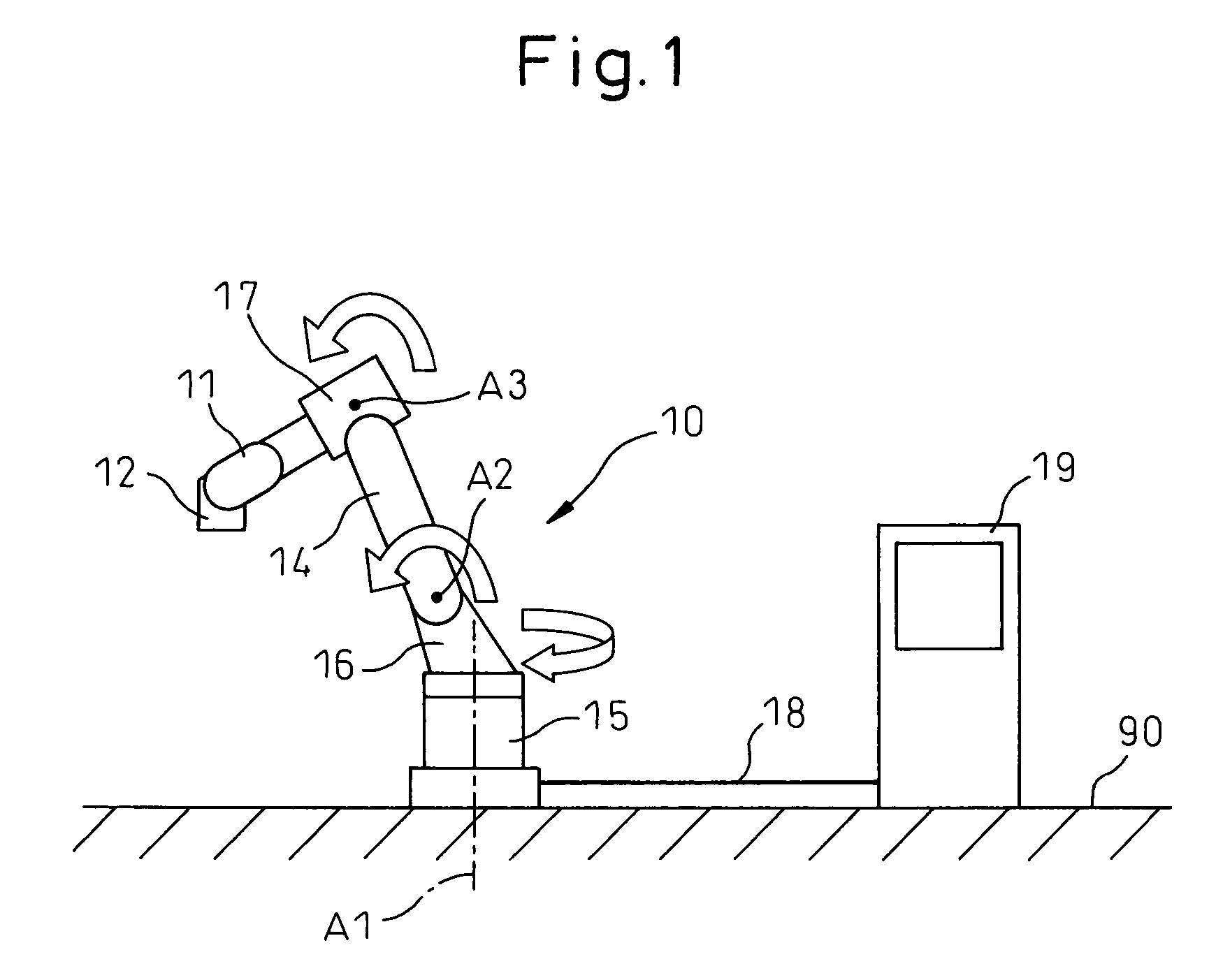
[0030]FIG. 1 is a side view of an ordinary industrial robot. As shown in FIG. 1, an industrial robot 10 includes a robot base 15 fixed to the floor 90, a turning body 16 rotatably mounted on the robot base 15, an upper arm 14 extending from the turning body 16 and a front arm base 17 mounted in the neighborhood of the upper end of the upper arm 14.

[0031]A first wrist element 11 is mounted at the forward end of the front arm base 17, and a second wrist element 12 is mounted on the first wrist element 11. A working means such as a holding hand (not shown) is mounted on the second wrist element 12. The wrist elements 11, 12 determine the posture of the working means in the space. The robot 10 is ...


PUM


Abstract

An industrial robot (10) comprising three power transmission units (21, 22, 23) arranged concentrically and three drive means for driving the three power transmission units, respectively, is disclosed. The drive means for at least one of the three power transmission units includes two motors (31, 34). Also, all of the three power transmission units and the three drive means are desirably built into the base (15) of the industrial robot. This configuration makes it possible to have high-duty operation with a comparatively compact structure.

Description

[0001]This application claims priority under 35 U.S.C. §119 and / or §365 to Japanese Application No. 2006-235393, filed on Aug. 31, 2006, the entire contents of which are incorporated herein by reference.BACKGROUND OF THE INVENTION[0002]1. Field of the Invention[0003]This invention relates to an industrial robot, or in particular to an industrial robot required to operate at high speed for a long period of time.[0004]2. Description of the Related Art[0005]FIG. 7 is a perspective view showing three power transmission units of a conventional industrial robot. As shown in FIG. 7, power transmission gears 124, 125, 126 are arranged in that order coaxially on three power transmission units 121, 122, 123, respectively, arranged concentrically with each other. The three power transmission gears 124, 125, 126 are engaged by motor gears 131, 132, 133 of motors 151, 152, 153, respectively. The motors 151, 152, 153 have the same rating. As can be seen from FIG. 7, the motor gears 131, 132, 133 ...

Claims


Application Information

Patent Timeline
Patent Type & Authority Patents(United States)
IPC IPC(8): B25J17/00
CPCB25J9/046B25J9/104Y10T74/20305
Inventor TAMURA, TOSHINARIKUREBAYASHI, HIDENORITANAKA, YASUYOSHI
Owner FANUC LTD
Why Eureka
Try Eureka