
Apparatus for positioning a medical instrument

a surgical instrument and apparatus technology, applied in the field of apparatus for positioning surgical instruments, can solve the problems of affecting the performance affecting the accuracy of the surgical instrument, and the limited amount of room for manipulating the instrument, so as to reduce the number of instruments needed and be less cumbersome

Inactive Publication Date: 2010-03-09
LAPAROCISION
View PDF25 Cites 1143 Cited by
  • Summary
  • Abstract
  • Description
  • Claims
  • Application Information

AI Technical Summary

Benefits of technology

The system enables precise and stable positioning of surgical instruments, reducing the risk of misdirection and operating room congestion, while allowing for single-handed or foot-activated operation, thus enhancing surgical efficiency and safety.

Problems solved by technology

However, this is especially true for minimally invasive endoscopic surgical procedures, such as laparoscopic surgery, in which the doctor has a limited amount of room to maneuver the instrument.
Endoscopes are presently hand held or positioned with complicated and expensive devices.
The scrub nurses have other tasks to perform, and holding the scope interferes with performing these tasks.
It is also difficult for the surgeon to direct others to position the scope for the best view.
When the surgeon does not hold the scope, it is often misdirected.
This can result in injury to the patient and delays in the conclusion of the surgery.
However, these arms face many of the same problems encountered when the laparoscope is held by hand.
Additionally, these robotic systems can take up too much space in the operating room and require someone to constantly monitor and operate it.
This unnecessarily ties up one of the members of the operating team and can contribute to crowding of the operation site.
This creates a geometrical challenge to maintain an X and Y-axis pivot point at the incision of the abdominal wall and a stable image.
Typically the above mentioned complicated and expensive mechanical linkages that extend over the patient are used to accomplish this positioning without any shaking of the image.

Method used


Image

  • Apparatus for positioning a medical instrument
  • Apparatus for positioning a medical instrument
  • Apparatus for positioning a medical instrument

Examples


Embodiment Construction

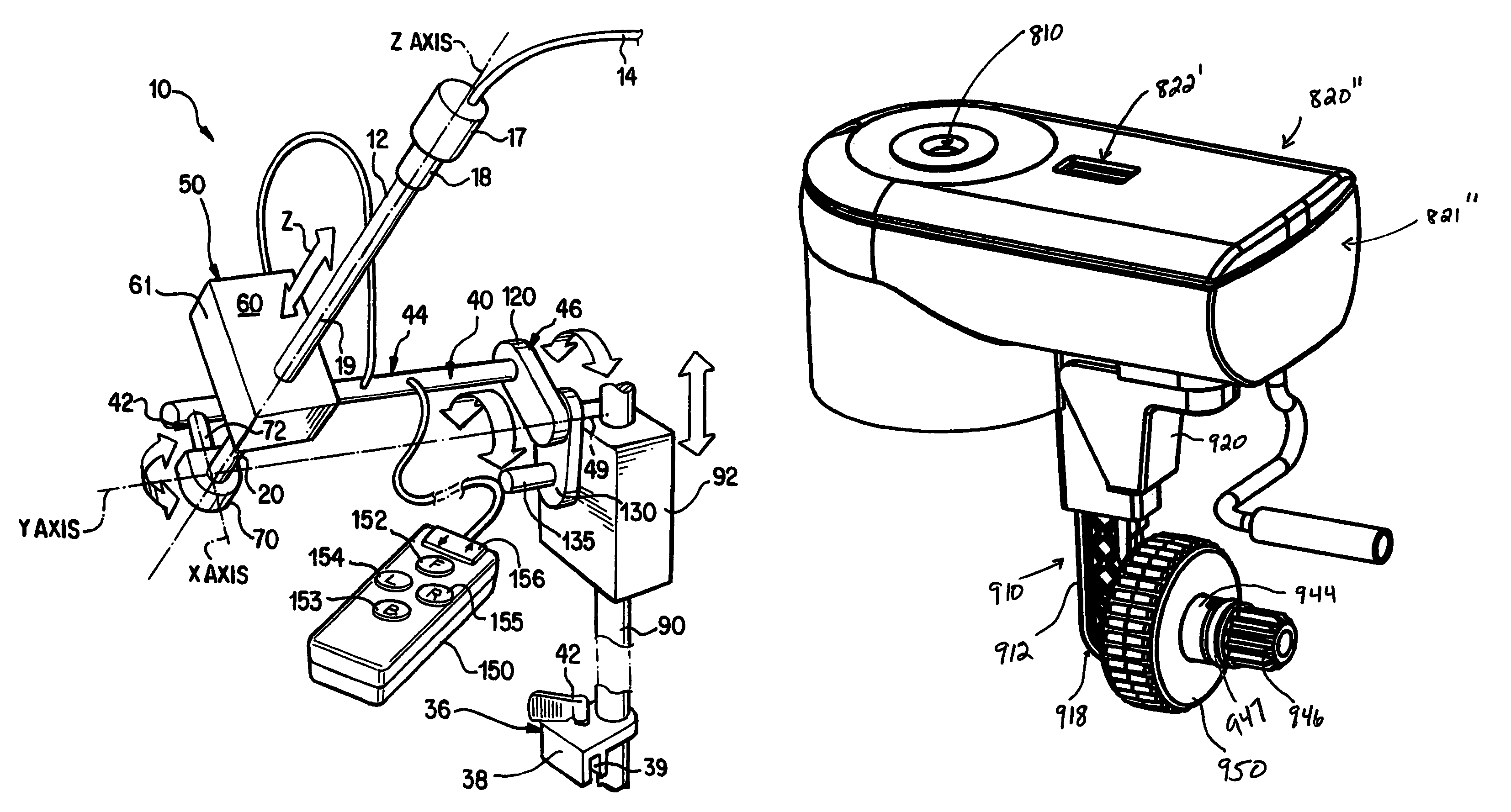
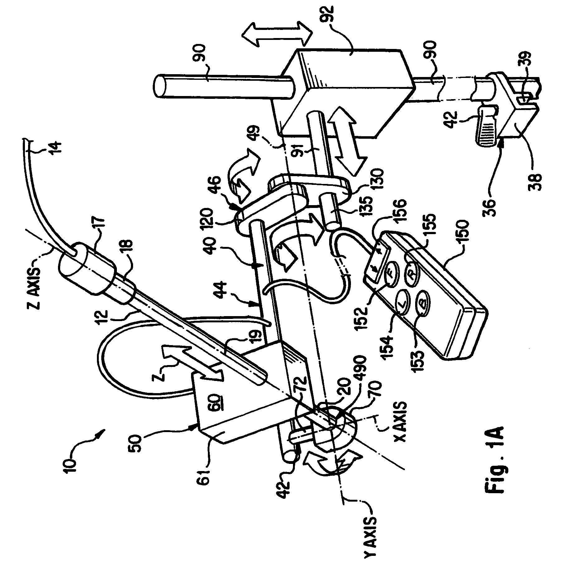
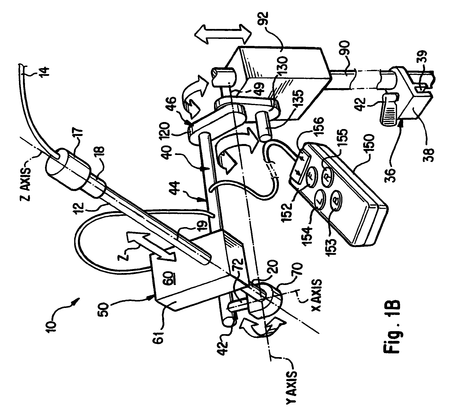
[0062]FIGS. 1A and 1B show an apparatus 10 for supporting and positioning a conventional medical instrument 12 relative to an operating table that has an equipment mounting member or a horizontally extending edge to which the apparatus 10 can be secured. Embodiments of such an apparatus 10 are discussed in U.S. Provisional Patent Application No. 60 / 376,848, which is hereby incorporated by reference. Known medical instruments 12 include graspers, forceps, cauterizing devices, endoscopes and all other instruments used in endoscopic procedures. In other embodiments, the medical instrument 12 can include a drill, a trocar or other piercing device. For ease of explanation and clarity, the following description of the present invention will discuss the apparatus 10 and how it positions and supports an endoscope, specifically a laparoscope. However, the following discussion is not limited to laparoscopes. Instead, it is equally applicable to other endoscopes and other medical equipment tha...


PUM


Abstract

The present device provides an apparatus for securely positioning a medical instrument relative to a patient. The apparatus comprises a drive assembly for moving the medical instrument along a first axis that is substantially parallel to the length of the instrument; an adapter comprising an elongated member and a pair of cooperating hubs for connecting the drive assembly to a positioning system. The cooperating hubs serving to allow separation of sterile from non sterile components. The positioning system comprises two motors each for moving the instrument about a different axis than the drive assembly. The apparatus moving the instrument about a point which is external to the patient. The device further comprises a sterile bag which encloses the positioning system, the bag having at least one opening for receiving an axel from a sterile adapter assembly, thereby rendering the entire apparatus sterile.

Description

[0001]This application claims the benefit of the filing date pursuant to 35 U.S.C. §120 of Application Ser. No. 60 / 580,724, filed Jun. 21, 2004 entitled APPARATUS FOR POSITIONING A MEDICAL INSTRUMENT RELATIVE TO A PATIENT and which in turn is a continuation-in-part of and claims the benefit of the filing date pursuant to 35 U.S.C. § 120 of application Ser. No. 10 / 428,069 filed May 2, 2003 now U.S. Pat. No. 7,347,862, entitled APPARATUS FOR POSITIONING A MEDICAL INSTRUMENT RELATIVE TO A PATIENT, the disclosure and content of which is hereby incorporated by reference in its entirety, which in turn claims the benefit of the filing date pursuant to 35 U.S.C. § 120 of U.S. Provisional Application Ser. No. 60 / 376,848 filed May 2, 2002 entitled APPARATUS FOR POSITIONING A MEDICAL INSTRUMENT, and U.S. Provisional Application Ser. No. 60 / 427,572 filed Nov. 20, 2002 entitled APPARATUS FOR POSITIONING A MEDICAL INSTRUMENT, and U.S. Provisional Application Ser. No. 60 / 441,127 filed Jan. 21, 200...

Claims


Application Information

Patent Timeline
Patent Type & Authority Patents(United States)
IPC IPC(8): A61B19/00A61B17/00A61B17/34A61B19/08
CPCA61B17/3403A61B19/26A61B19/081A61B19/201A61B19/22A61B2017/347A61B2017/3409A61B34/70A61B90/50A61B90/11A61B46/10
Inventor LAYER, JAMES H.
Owner LAPAROCISION
Learn More