Network terminal with means for wirelessly establishing secure private link with external terminal

a network terminal and secure private connection technology, applied in the field of communication technology for interconnection of data processing terminals, can solve the problems of disadvantageous prior art and difficulty in installing a radio transceiver on each lan terminal

Active Publication Date: 2010-03-09
NEC CORP
View PDF20 Cites 35 Cited by
  • Summary
  • Abstract
  • Description
  • Claims
  • Application Information

AI Technical Summary

Problems solved by technology

Since the high-precision RF (radio frequency) transceivers represent a significant amount of expenditure, this prior art is disadvantageous for a local area network if the user desires to additionally establish an individual wireless link between a mobile terminal and a nearby LAN terminal.
Furthermore, due to the characteristics of the high-precision transceiver, difficulty will be experienced when installing a radio transceiver on each LAN terminal.
This is disadvantageous for applications where secure communication is important.

Method used


Image

  • Network terminal with means for wirelessly establishing secure private link with external terminal
  • Network terminal with means for wirelessly establishing secure private link with external terminal
  • Network terminal with means for wirelessly establishing secure private link with external terminal

Examples


first embodiment

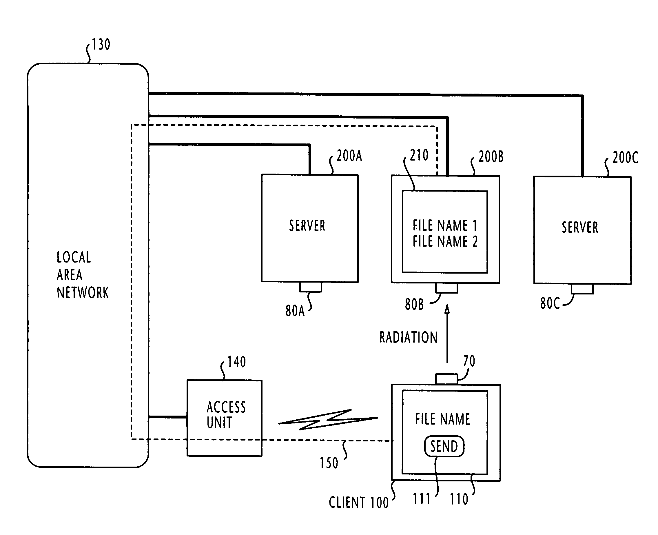
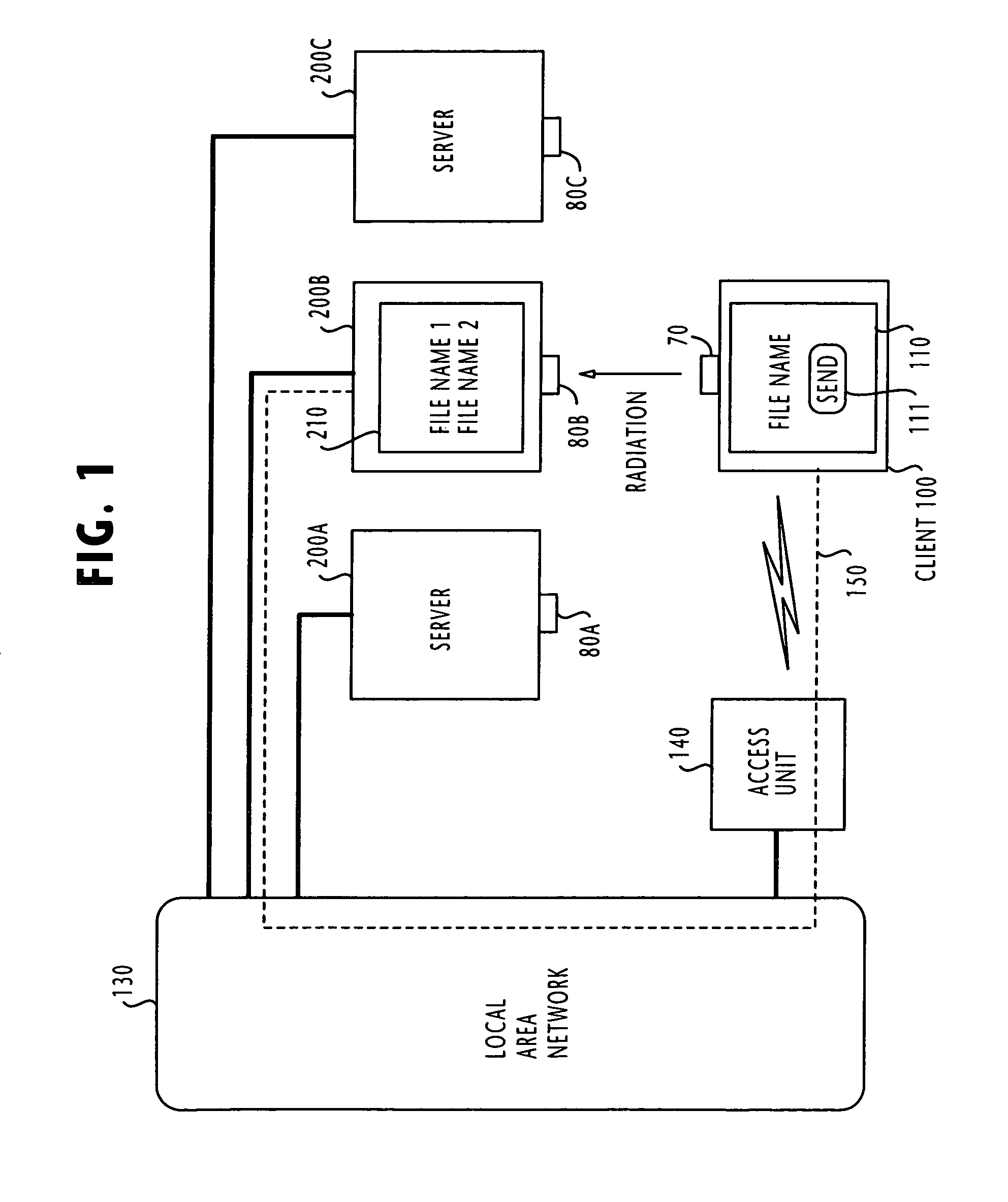
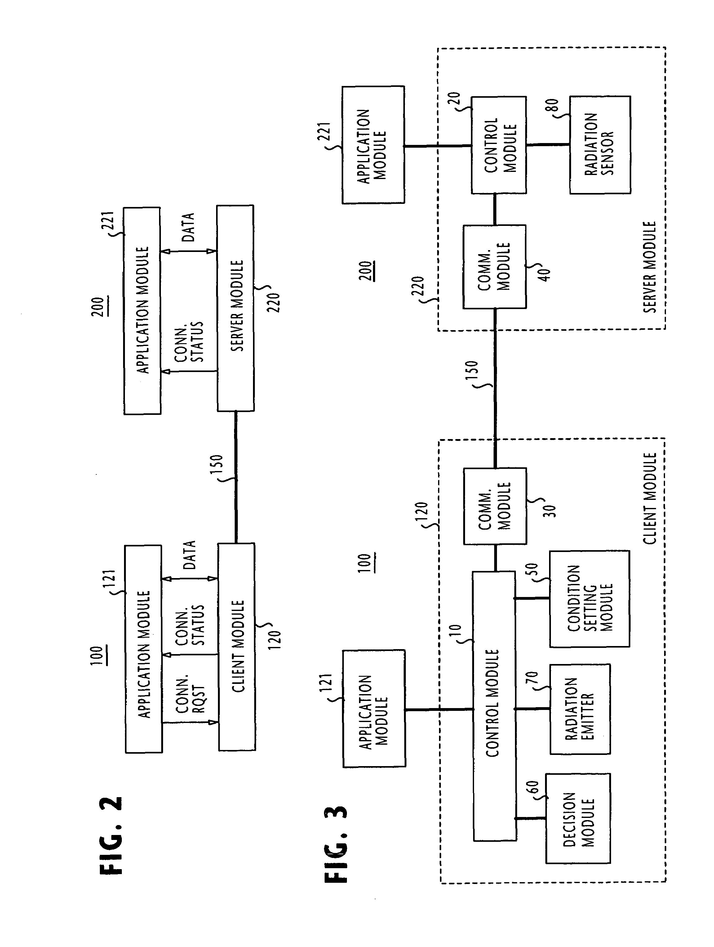
[0052]Referring to FIG. 1, there is shown a communications network which is suitable for implementing the present invention. The network comprises a plurality of server terminals 200A, 200B and 200C, all of which are connected to a local area network 130. A wireless access unit 140 is also connected to the local area network to establish a wireless link to the mobile client terminal 100, which is located close to the server terminal 200B, for example. Therefore, the client terminal 100 is also connected to the LAN 130. Client terminal 100 is now conditioned to establish a logical link, or session to any of the server terminals. If the client terminal 100 is positioned close to the server terminal 200B, as illustrated, a session 150 can be established to it through the LAN 130.

[0053]Client terminal 100 is provided with a radiation emitter 70 for producing a beam of infrared light of a predetermined intensity and each server terminal 200 has a radiation sensor 80 for receiving infrare...

second embodiment

[0090]A communications network which is suitable for implementing the invention is illustrated in FIG. 24. In this network, only one server terminal 200 and a plurality of client terminals 100A, 100B and 100C are provided. Between the server terminal and only one of the client terminals that is nearest to it, a session 150 is established via the LAN 130 and wireless access unit 140, even though a wireless link is established between each client terminal and the access unit 140.

[0091]The network of this type can be used to transmit a message, or commercial advertisement, shown in the server's user interface 210 to the user interface 110 of the nearest client terminal 100A when the user touches a RQST (request) button 111 on the user interface 110.

[0092]Prior to the establishment of a session, the server terminal 200 broadcasts its network address over the LAN 130 in response to a request from the application module so that all client terminals are informed of the network address of t...


PUM


Abstract

In a communications network where first and second communication terminals are interconnected via a common communication medium such as a local area network, the terminals jointly establish an infrared light private communication link if they are brought close to each other. The first and second terminals communicate their network addresses to each other either via the local area network or via the private communication link, and establish a session between the communicated network addresses via the local area network if the strength of the infrared-light private communication link at the receiving end is higher than a decision threshold.

Description

BACKGROUND OF THE INVENTION[0001]1. Field of the Invention[0002]The present invention relates generally to communications technology for interconnecting data processing terminals including personal computers and mobile data terminals, and more specifically to a technique for establishing a session between such terminals in a client-server relationship when a predetermined mutual proximity is satisfied.[0003]2. Description of the Related Art[0004]While data communications technology has evolved from long-haul peer-to-peer connections and progressed through LAN and WAN to the recent internet connections, study has recently been focused on a technology for establishing secure connections between data terminals mutually located at close range. Because of the increasing importance of security, this technology will open up ways for developing a wide range of future applications. Typical examples of the prior art technology for establishing close-range connections involve the use of a wire...

Claims


Application Information

Patent Timeline
Patent Type & Authority Patents(United States)
IPC IPC(8): H04W4/00H04L12/28G06F13/00
CPCH04W12/02H04W8/005
Inventor NAKAO, TOSHIYASUKASHITANI, ATSUSHIHAYAKAWA, KEISUKETAKAHASHI, MIE
Owner NEC CORP
Why Eureka
Try Eureka